
Travel & Drive Components
The wheels and drives
that move the crane.
Crane wheels, end carriages, trolley travel motors and brake gearmotors. Explore complete travel mechanisms or identify the motor, gearbox and connection parts you need.
Different wheel paths.
Different drive layouts.
Start with how the equipment is supported and driven. These common configurations describe more than one design choice: an underhung unit, for example, can also use geared wheels.
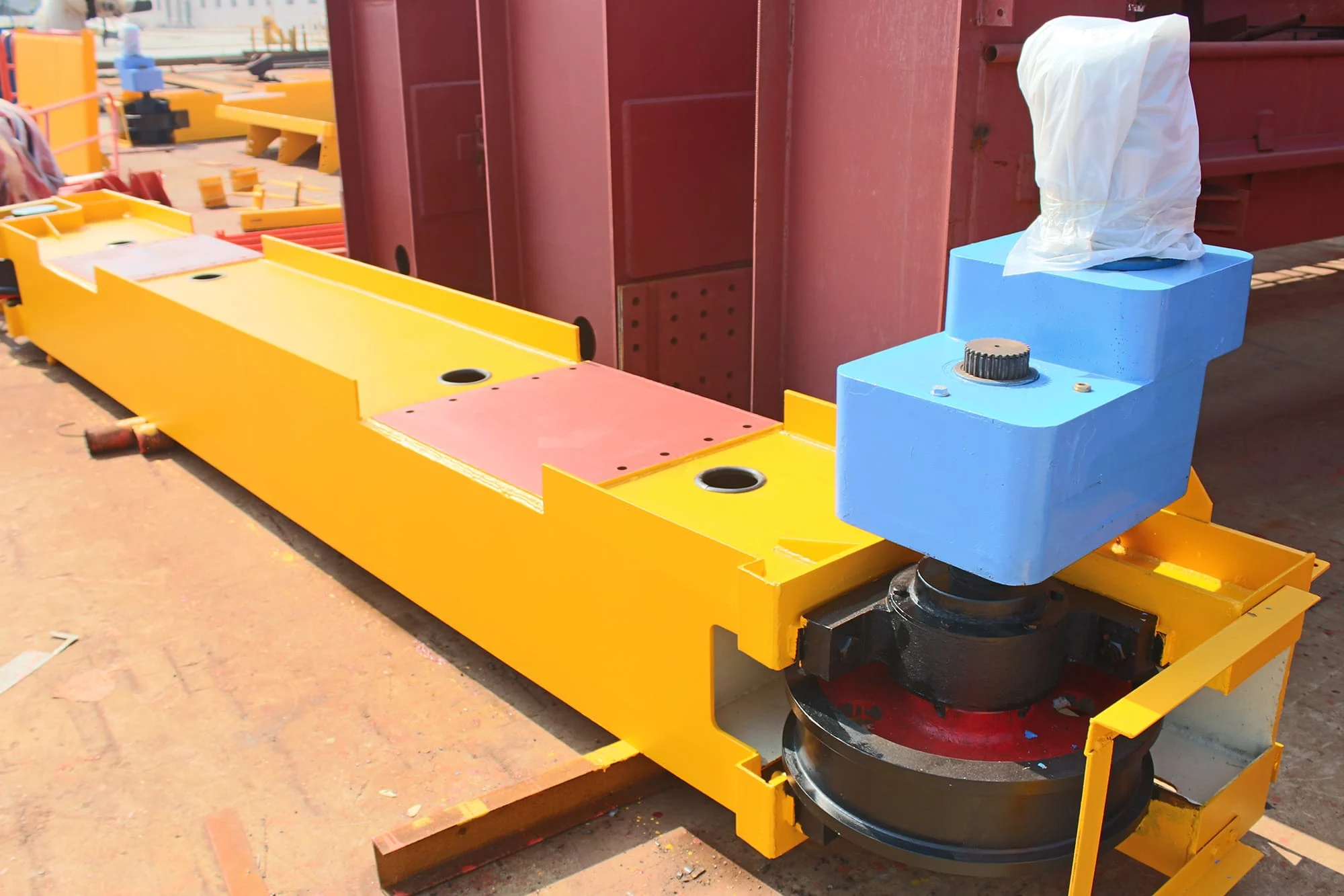
Wheel blocks & end carriages
A geared motor connects to the wheel shaft without an external wheel gear ring. A housed wheel block can be supplied separately or built into an end carriage.
Design differences & options
- Hollow-shaft or coupled arrangements keep the drive close to the wheel. Output connection, torque support and removal space depend on the selected design.
- Wheel blocks may use top, side, pin or end connections. Available connections vary by size and manufacturer.
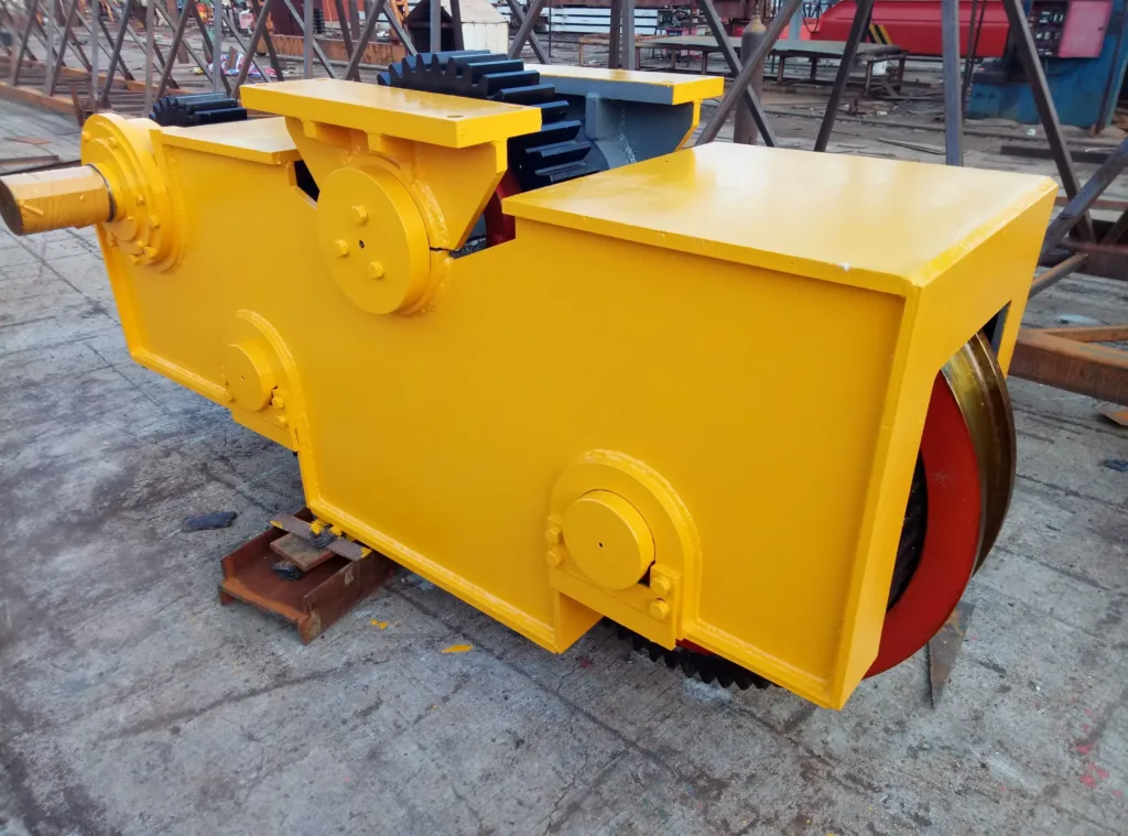
Open-gear travel units
A pinion meshes with gearing on the wheel. This arrangement appears in end carriages and trolley travel units; the photo shows a larger geared assembly.
Design differences & options
- The wheel gear, pinion and their alignment form part of the drive. Access for inspection, lubrication and guarding must be considered.
- Identify the gear geometry as well as the wheel profile. A plain wheel and a geared wheel are different replacement parts.
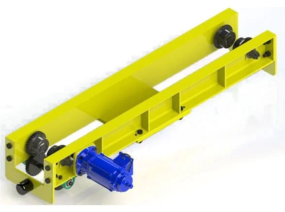
Underhung end carriages
Paired wheels travel on the lower flange of the runway beam. The end carriage hangs below its support instead of running on a rail above it.
Design differences & options
- Flat or tapered wheel treads must suit the beam flange. Flange width, thickness and available adjustment affect the fit.
- Geared motor and speed-control choices depend on the arrangement. Underhung describes the support geometry, not a separate motor technology.
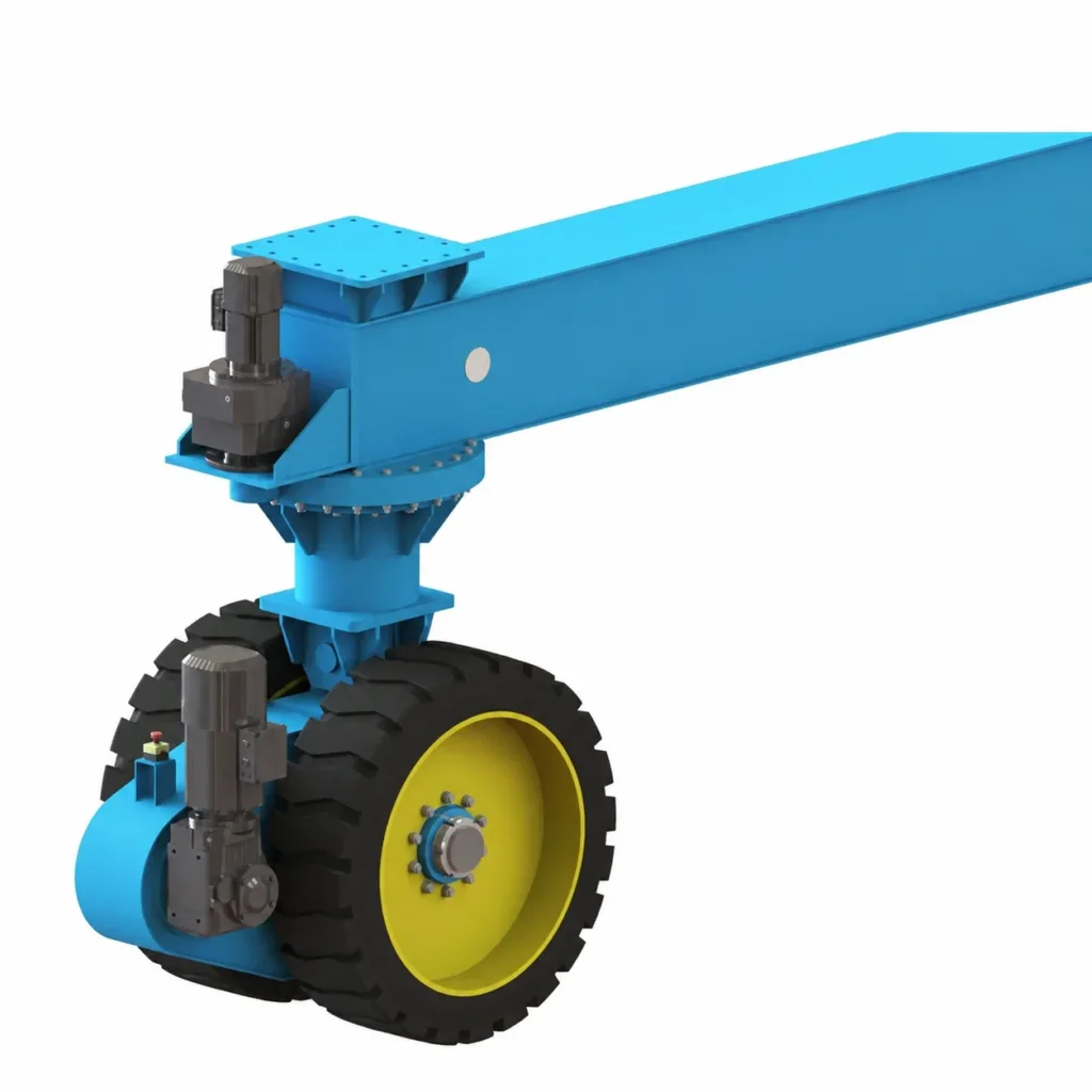
Rubber-tyred travel units
Tyres carry the equipment on the ground. Travel and steering are separate functions, with the tyre, steering system and power supply selected for the route.
Design differences & options
- Solid or pneumatic tyres and electric or hydraulic steering are design choices. Steering angles and operating modes depend on the complete machine.
- Ground bearing capacity, gradients, turning space and outdoor exposure matter. This illustration shows wheel and steering drives, not a complete vehicle.
Replace a motor.
Or the complete drive.
Order a combined motor, gearbox and brake, or replace an individual component. Show which parts of the existing drive you intend to keep.
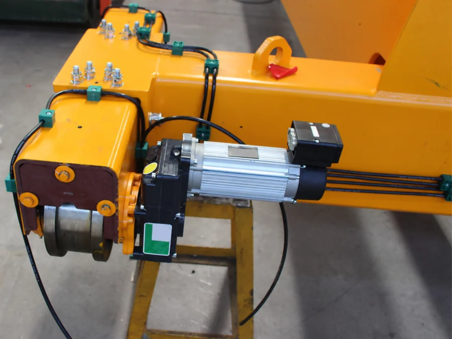
Brake gearmotors
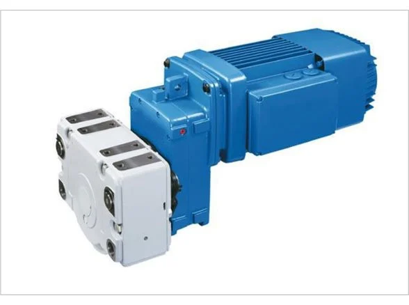
Often called three-in-one travel drives. The photo shows a combined drive installed on an end carriage; the structural beam is a separate supply item.
What to match
- Match the output connection to the wheel shaft or pinion. Include mounting position, torque support and space for installation and removal.
- Provide the ratio or output speed, motor plate, brake specification and control method. A geared motor is not necessarily supplied with a brake.
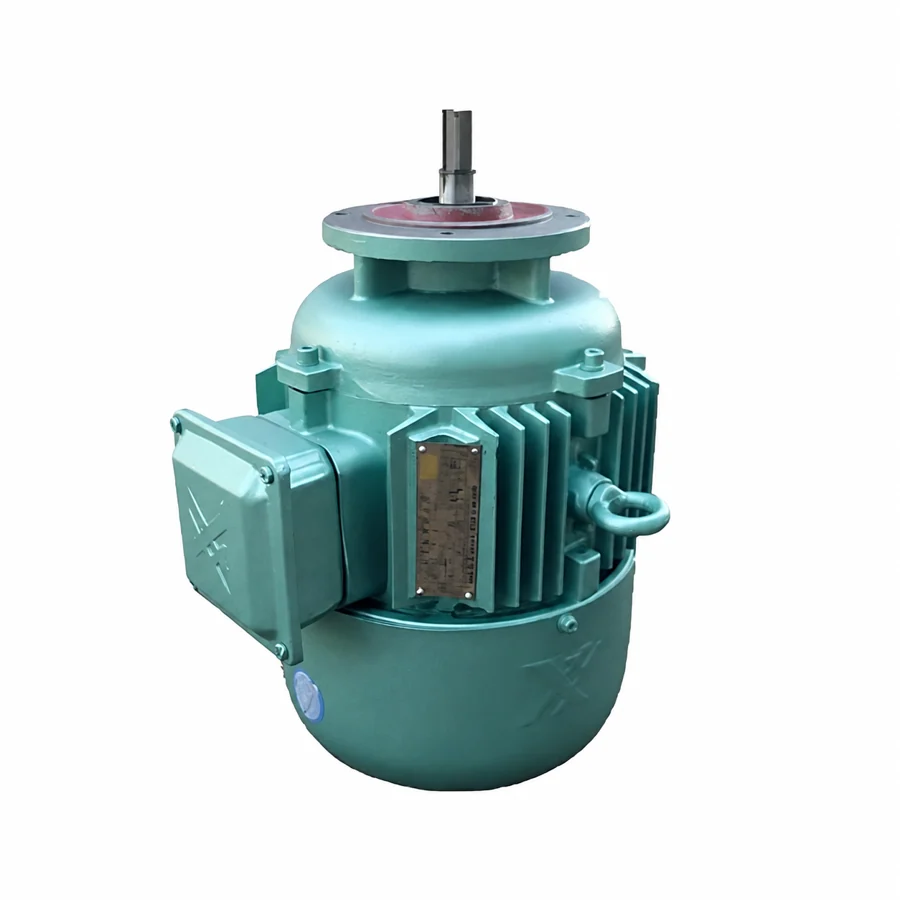
Travel motors
Move the trolley across the bridge or the crane along its runway. The photo shows a separate motor; the gearbox and wheels are not included.
What to match
- Send the complete model, power, speed, voltage and duty from the nameplate. Identify single-speed, two-speed or inverter operation and the original braking arrangement.
- Show the flange, shaft end and connection to the retained transmission. The same motor power does not establish replacement fit.
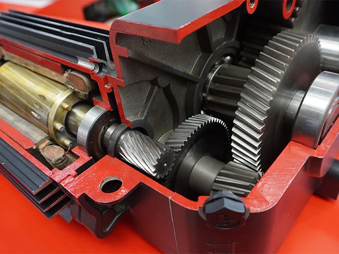
Travel gearboxes
Connect the motor to the driven wheels. This cutaway shows the internal transmission; identify the complete gearbox or specific connection part required.
What to match
- Match the reduction ratio, output speed, input/output shaft connections, mounting position and wheel-side drive. Use the original reference or drawing.
- List any separate brake, coupling, pinion or torque support required. These may be separate items or part of the matched drive package.
From an individual wheel
to a complete travel unit.
A wheel set combines rotating parts with their supports. This photo shows split bearing housings; a compact wheel block uses a different housing arrangement.
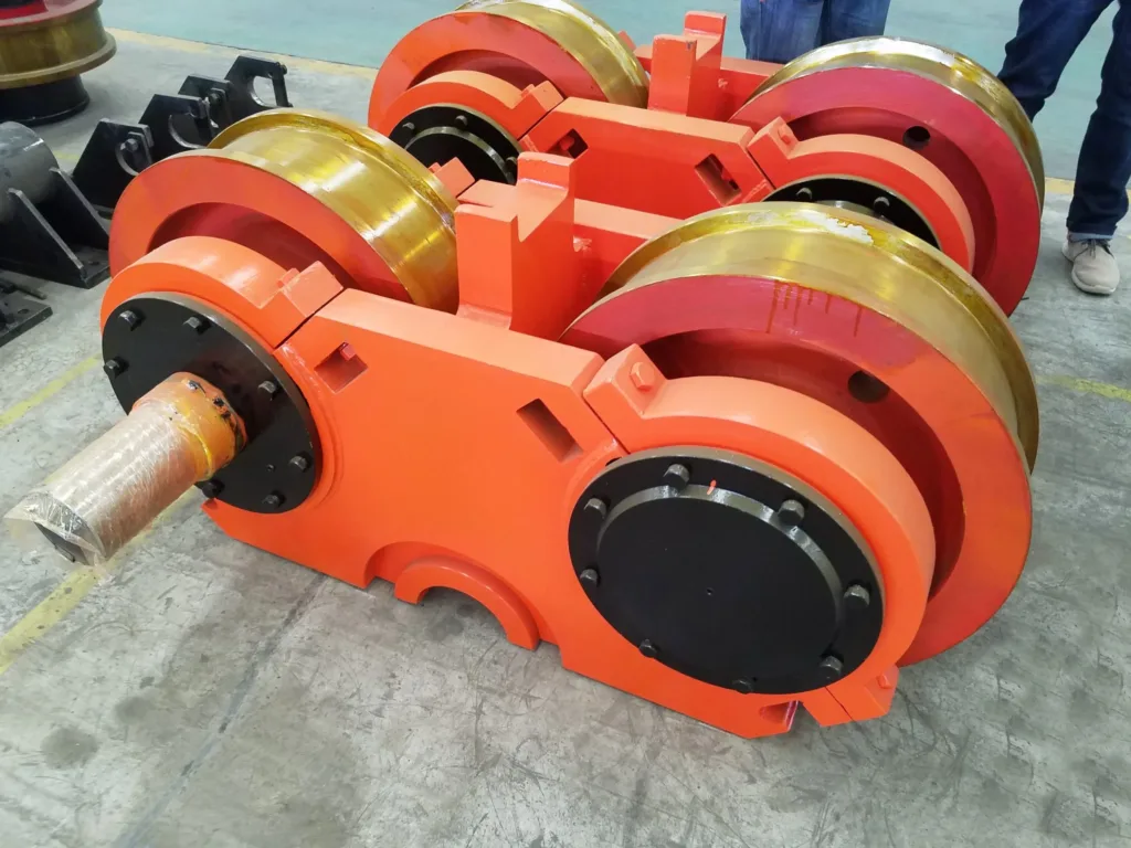
01Wheel set, wheel block or end carriage?
A wheel set includes an agreed combination of wheel, shaft and bearings. A wheel block adds a housing with defined connections. An end carriage adds the structural beam and wheel spacing; a multi-wheel bogie adds an articulated support arrangement. Drives, buffers and connecting hardware must be listed in the supply scope.
02Which travel accessories are available?
Buffers, rail sweeps, travel limits, warning devices and anti-collision equipment may be specified around the mechanism. Outdoor cranes can also need wind restraints such as rail clamps. These are selected functions, not standard inclusions in every end-carriage package.
Workshop bridges.
Multi-wheel gantries.
The load path determines how the travel assemblies connect to the machine. The examples below show two different structural arrangements.
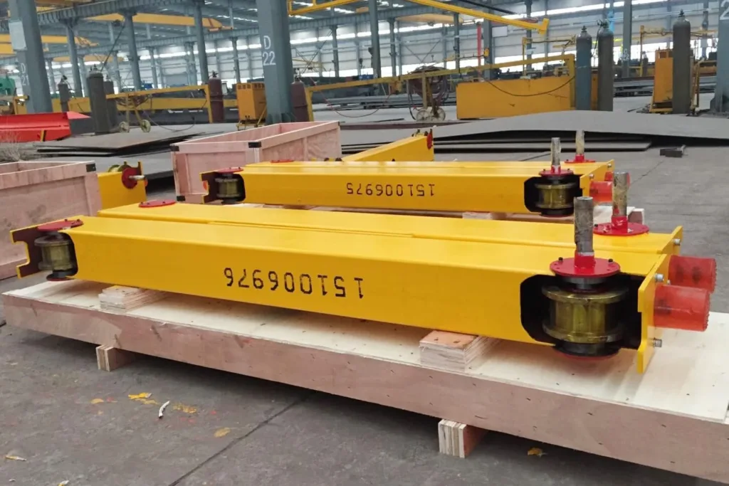
End carriages at the bridge ends
End carriages carry the bridge along its runways. Wheelbase, bridge attachment and end approach are coordinated with the crane layout.
Design differences & options
- Top, side or other bridge connections need defined mating surfaces and fasteners.
- Wheel blocks can also move a trolley across the bridge, using a different frame and rail spacing.
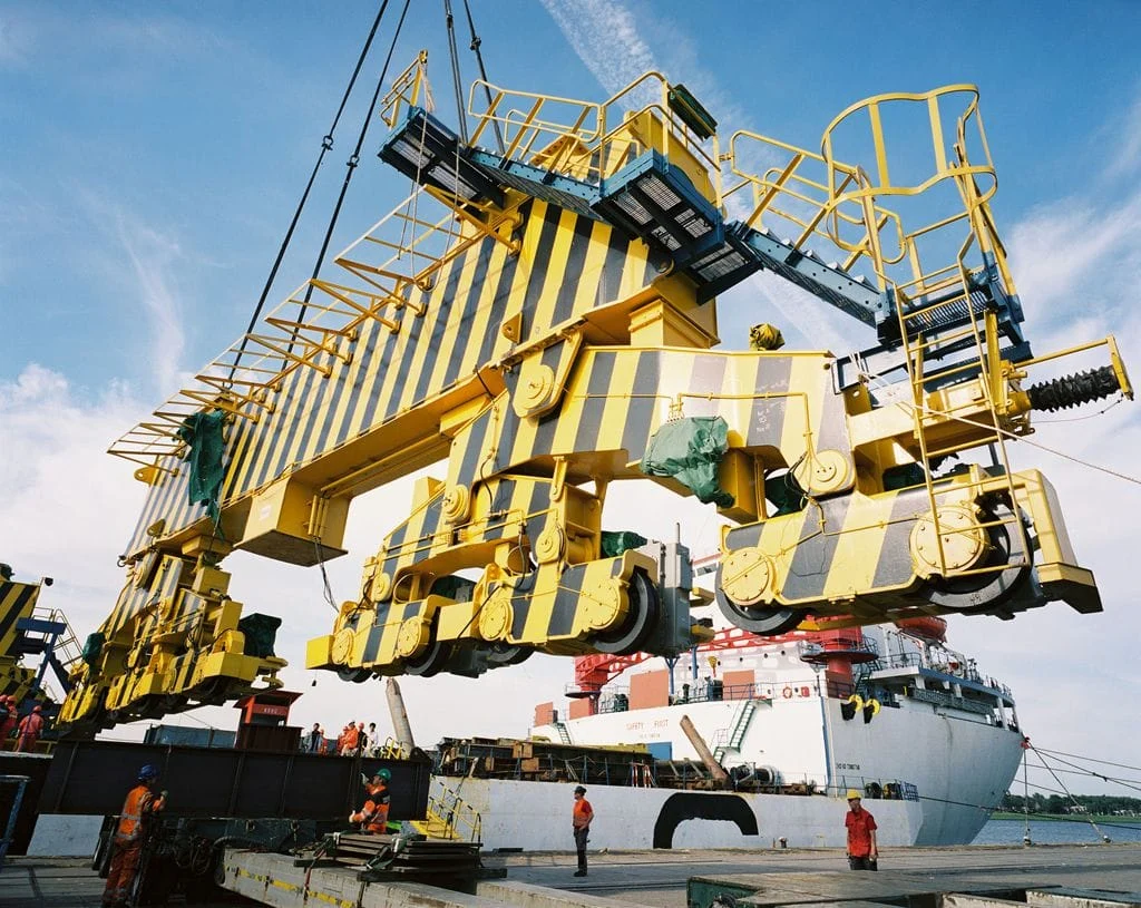
Multiple wheels on bogies
Articulated bogies connect several wheel assemblies to a larger support. Wheel numbers and articulation follow the loading and rail layout.
Design differences & options
- Individual wheel loads and supporting joints must be established by the machine design.
- Rail-running bogies and rubber-tyred units serve different routes. Complete transfer vehicles have a separate product range.
Need matching rails?
Review the rail profile, fastenings and supporting runway alongside the wheel arrangement.
Explore rails & runwaysIdentify the mechanism.
Then confirm the match.
An overall photo, close-ups and the nameplates are useful starting points. Send existing drawings where available.
01Is the same wheel diameter or model code enough?
No. Tread and flange geometry, shaft fits, housing connections and gearbox interfaces can differ. Compare drawings before treating wheel blocks or drives as interchangeable.
02Will replacing the wheels solve uneven wear?
Not necessarily. Wheel alignment, rail geometry, drive coordination and supporting structure can contribute to wear or rail biting. Include photos of the wear and describe when it occurs.
03What should the quotation confirm?
The selected arrangement, included parts, interface drawing and required operating conditions. State any material documentation, inspection records or certificates needed; these must be confirmed for the actual supply.
A replacement part.
Or a new travel assembly.
Tell us the required quantity, destination and timing. We will review the mechanism and the information needed to define the supply.
Discuss travel components- Photos, markings, drive nameplates and available drawings.
- Layout, wheel loads, speed, duty and operating environment.
- Parts to replace, equipment to retain and steelwork supplied by others.