
Port, Marine & Infrastructure Systems · Product family
Connect the cargo.
Across the interface.
Large-load systems begin where vessel, quay, yard, dock, deck or civil works meet the cargo. The operating route, fixed interfaces, environment, controls and release evidence establish the product family.
- 01
- 02
- 03
- 04
- 05
Choose the operating route.
Then the equipment.
Six product families cover vessel exchange, yard stacking, terminal transport, harbour cargo, marine construction and civil-infrastructure lifting. Start with the real movement and interface, then select the equipment.
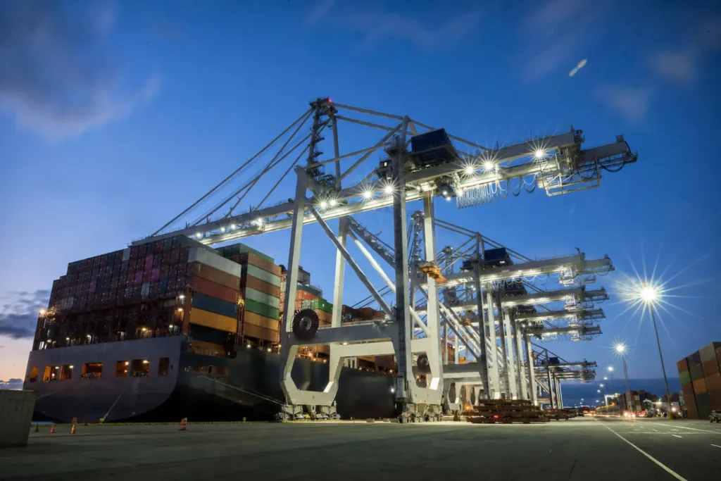
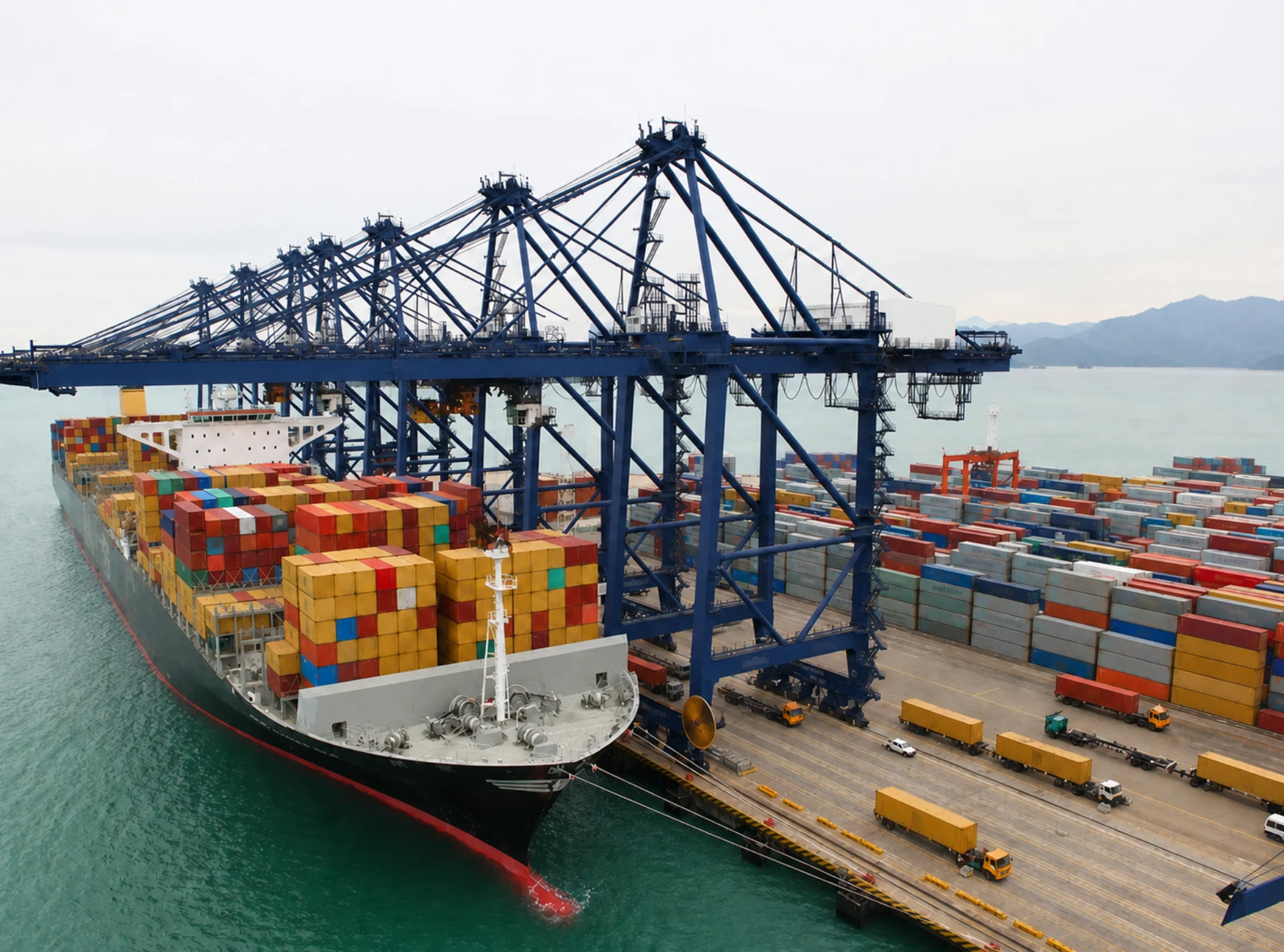
Quayside Container Cranes
Ship-to-shore and quayside container handling systems for vessel interfaces.
- Vessel bay, hatch and outreach envelope
- Spreader, waterside and landside transfer interface
- Wind, corrosion, access and terminal control boundary
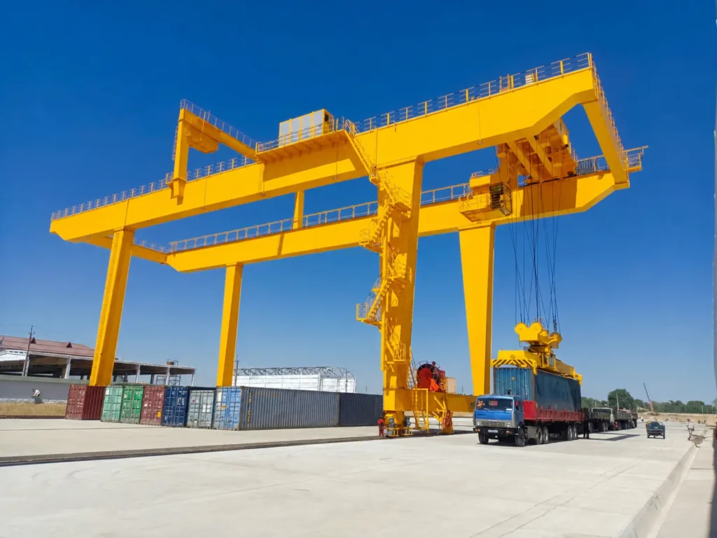
Container Yard Cranes
RMG, RTG and related yard crane formats for container stacking and transfer interfaces.
- RMG, RTG and automated yard formats
- Block width, stack height, truck or interchange lanes
- Rail or tyre interface, power, traffic and control
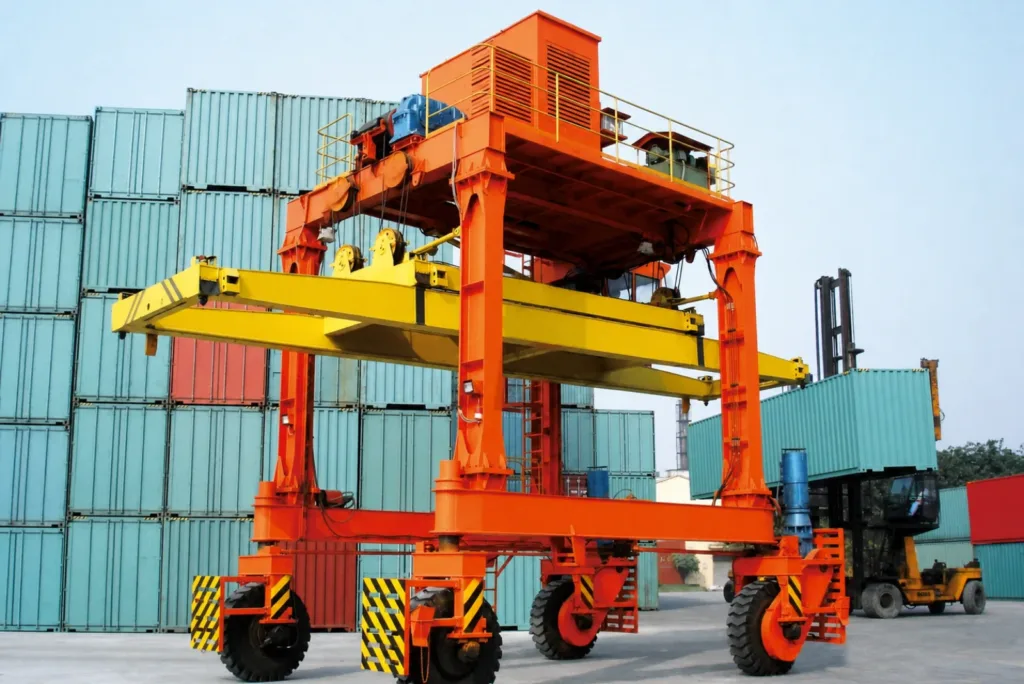
Container Horizontal Handling
Straddle-carrier and automated horizontal transport routes between quay, yard and interchange points.
- Straddle-carrier and terminal-horizontal transport
- Quay, yard and interchange route continuity
- Container pickup, traffic, charging or fuelling and recovery
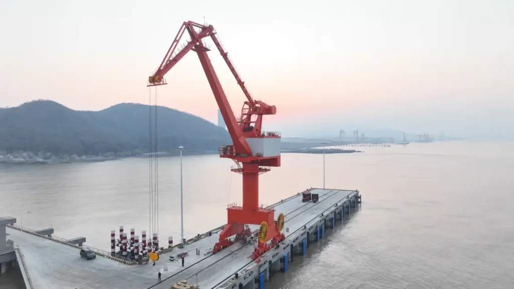
Harbour Portal & Bulk Cranes
Portal and bulk-handling cranes for harbour, grab and process-transfer duties.
- Container, grab, hook and general-cargo duties
- Mobile, rail-mounted or fixed harbour interfaces
- Cargo cycle, vessel reach, quay capacity and attachment
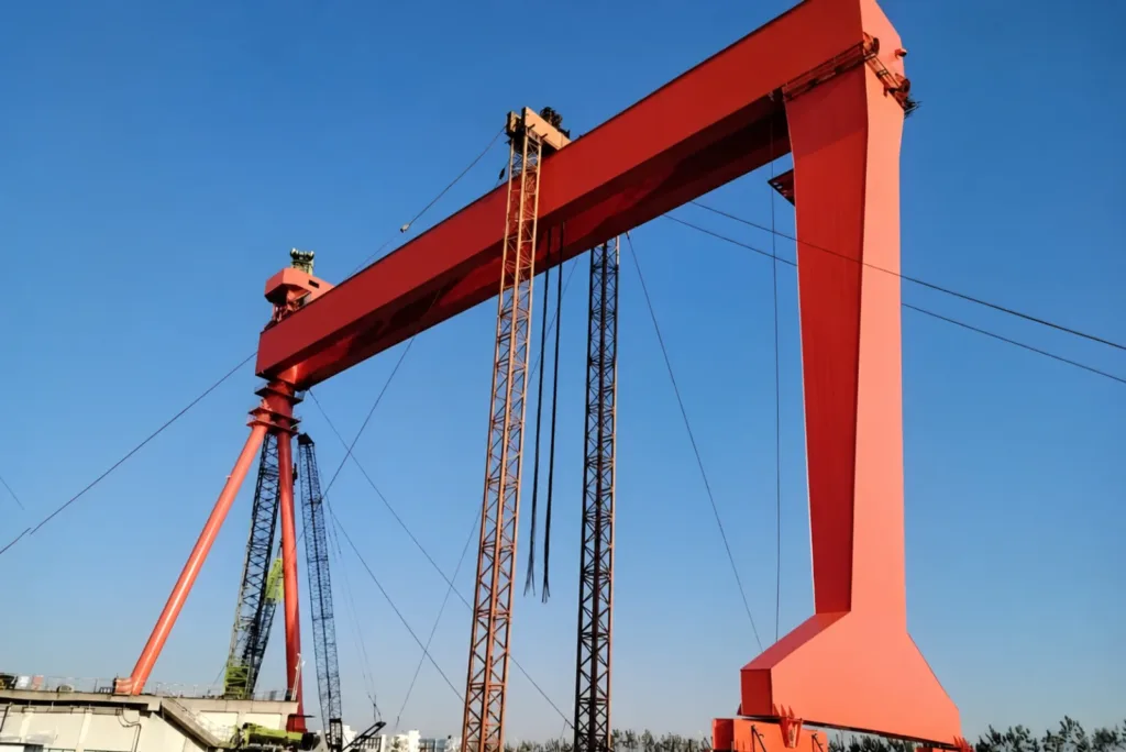
Shipyard, Marine & Offshore Cranes
Shipbuilding, vessel-service, marine and offshore lifting formats for defined environments.
- Ship blocks, modules, vessel service and offshore lifts
- Large-span, deck, pedestal or marine support formats
- Wind, corrosion, access, redundancy and lifting procedure
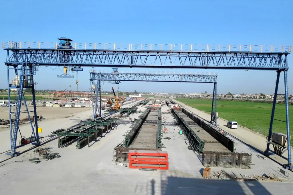
Bridge, Precast & Infrastructure Lifting
Bridge launching, beam, segment and precast handling systems for civil projects.
- Beam, segment, mould and precast handling
- Casting yard, launching and site erection interfaces
- Synchronous lift, temporary works and civil release
Compare the route.
Not a headline capacity.
The matrix identifies the operating and fixed interfaces that change scope. Ratings, standards and acceptance evidence remain tied to destination and project inputs.
Six recognisable tasks.
Six application examples.
Describe what crosses the vessel, yard, harbour, dock or civil interface. Each task leads to one product family and a project-specific evidence brief.
Vessel geometry, quay interface and terminal hand-off establish the quayside system. 01Must containers move directly between a vessel bay and the quay?
Vessel class, bay and hatch geometry, outreach, lift height, apron width, waterside and landside transfer, quay rail and civil capacity, wind and terminal control define the quayside container-crane route.
Quayside Container CranesStart this product briefBlock geometry and interchange lanes decide between rail, tyre and automated yard formats. 02Is the main task stacking and exchanging containers inside defined yard blocks?
Stack height, rows, block length, truck or transfer lanes, moves per hour, relocation pattern, rails or pavement, wind, power and automation boundary establish the RMG, RTG or related yard-crane route.
Container Yard CranesStart this product briefThe terminal route and container hand-off—not warehouse navigation—define horizontal handling. 03Must containers travel between quay, buffer, yard and interchange points?
Container sizes, pickup and set-down method, route distance, crossings, traffic, peaks, spreader or chassis interface, charging or fuelling, dispatch and recovery define the horizontal terminal-handling system.
Container Horizontal HandlingStart this product briefCargo, attachment, vessel reach and quay interface establish the harbour crane. 04Does one berth handle bulk, general cargo, heavy lifts or several attachments?
Cargo density and flow, hook, grab or spreader, vessel reach, hopper or landside hand-off, duty cycle, quay capacity, mobility, power, wind and corrosion define the portal, mobile or fixed harbour-crane route.
Harbour Portal & Bulk CranesStart this product briefShip blocks, modules and marine environments require a lift system tied to structure and procedure. 05Must large blocks, modules or service loads move in a shipyard or marine environment?
Load support, tandem or multi-point lifting, span and height, dock, rail, deck or pedestal interface, wind, corrosion, access, redundancy, synchronisation and lift procedure establish the shipyard, vessel or offshore route.
Shipyard, Marine & Offshore CranesStart this product briefPrecast geometry, temporary works and the erection sequence define infrastructure lifting. 06Must beams, segments, moulds or precast units move from casting to erection?
Unit geometry, lift points, casting bed, storage, transporter, rail or temporary works, pier interface, synchronous control, route, civil acceptance and erection sequence define the gantry, launcher or lifting system.
Bridge, Precast & Infrastructure LiftingStart this product brief
Cargo. Interface.
release.
A crane or carrier is only one layer. Cargo engagement, fixed works, route, controls, safe state, testing and destination records must meet at a declared project boundary.
- 01
Record every physical exchange.
Cargo or container, mass, centre of gravity, engagement, vessel or site positions, travel path, duty, peaks and exception states establish the operating basis.
- 02
Prove the real installation boundary.
Quay, rail, pavement, dock, deck, temporary works, pier, power, traffic, access, wind, corrosion and other responsible parties define what the equipment can connect to.
- 03
Agree safe state and evidence.
Local and terminal controls, interlocks, power or network loss, storm state, recovery, tests, witnessing, destination standards, records and handover are defined before release.
Questions that change.
The system route.
These are buyer decisions that change equipment family, civil scope, terminal flow, quotation basis or acceptance evidence—not generic definitions.
01When should a terminal use a ship-to-shore crane instead of a mobile or portal harbour crane?
A ship-to-shore crane is normally the dedicated route when container-vessel bays, hatch geometry, outreach, lift height, apron flow and terminal container hand-off dominate the berth. A mobile, rail-mounted or fixed harbour crane can be more credible for mixed cargo, changing berth duties, bulk or general cargo and lower specialisation. Vessel calls, cargo mix, berth layout, quay capacity and required cycle—not crane capacity alone—decide the route.
02How do we choose between RMG and RTG container-yard formats?
Start with block width and length, stack height, interchange lanes, required moves, relocation strategy, civil works, rail or pavement condition, power, emissions, automation and future block changes. RMGs suit stable rail-based blocks and deep integration; RTGs retain block mobility but add tyre, steering, pavement and energy decisions. The choice must include terminal flow and civil scope.
03How do we choose between terminal transport equipment and warehouse mobile robots?
Use the operating route and hand-off points. Equipment that moves containers between quay, yard and interchange areas under terminal traffic and control rules belongs to the port-handling system. Warehouse and factory robots are selected around free navigation, pallet or tote handling and fleet coordination. Similar AGV technology may be used in both, but the real route and interfaces decide the solution.
04What berth, vessel, yard and civil information is needed before quotation?
Send vessel classes and working bays, tide or water-level range, quay and rail survey, permissible wheel loads, apron and yard layout, stack plan, traffic lanes, cargo or container data, required moves and peaks, wind and corrosion environment, power, control systems, maintenance access and destination. Unknown inputs can remain open, but they must be visible in the quotation boundary.
05Can one project include crane equipment, spreaders or grabs, horizontal transport and terminal controls?
Yes, if the supply and responsibility boundary is explicit. The review separates the crane or transport equipment, load-engagement attachment, civil and power interfaces, local controls, terminal-system hand-off, commissioning tests and records. One project interface does not mean every subsystem is manufactured by one party.
06How are wind, corrosion, marine environment and safe shutdown handled?
The project defines operating and out-of-service wind states, corrosion category and coating basis, storm parking or anchoring, brakes and restraints, lightning and power-loss response, retained-load state, access, rescue and restart authority. Offshore or vessel-mounted systems may add sea-state, motion, redundancy and class requirements. These are destination- and project-specific evidence, not blanket catalogue claims.
07What must be defined for a shipyard, offshore, bridge or precast lifting quotation?
Provide load geometry and lift points, centre of gravity, tandem or synchronous lift requirement, route and final position, dock, deck, rail, casting bed, temporary works or pier interfaces, wind or marine environment, duty, erection or production sequence, access and destination standards. A drawing, lift sketch and site plan are enough to begin the evidence map.
Send the interface.
We map the system.
A vessel or site plan, cargo data, operating route, quay, rail, dock, deck or civil information, duty, environment, control boundary and destination are enough to begin. The first review identifies credible equipment options and the missing interface or release evidence.
Define the system route- Container, load, mass, geometry and engagement
- Vessel, yard, dock, deck or site movement
- Quay, rail, pavement, civil works and access
- Cycles, peaks, wind, corrosion and marine state
- Power, traffic, hand-off, shutdown and recovery
- Destination, standards, project stage and records