
Crane Safety & Monitoring Devices
Know the load.
Set the limits.
Load limiters, travel and hoist limit switches, proximity sensors and warning devices. Select equipment for a new crane or match a replacement to the installed system.
Different signals.
Different jobs.
These devices can work together on one crane. Choose the function needed, then match the device and its connection to the machine.
Overload limiters
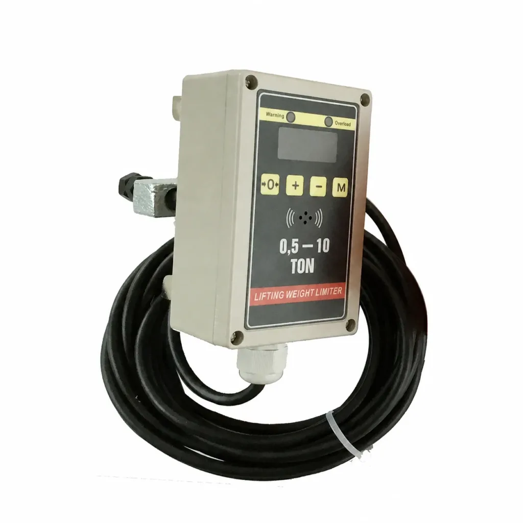
Measure the lifted load and send a signal when a configured limit is reached. The sensor and instrument must match the lifting mechanism.
Types & matching details
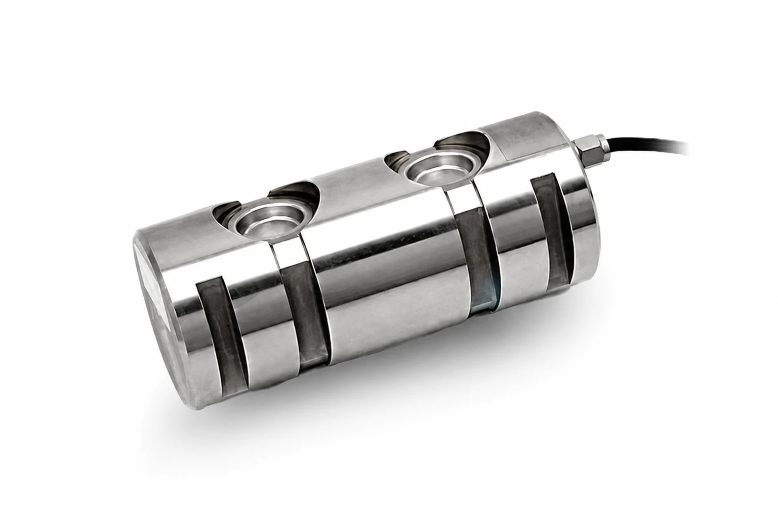
- Rope-clamp, load-pin and bearing-support arrangements suit different mounting points. Identify the rope diameter and reeving, pin dimensions or support arrangement as applicable.
- Choose the required display, sensor channels and alarm or limiting outputs. For main and auxiliary hooks, define separate readings and any combined-load function.
Hoist & travel limits
Detect a defined position in the hoisting or travel motion. The control circuit uses the signal for the specified slowdown or stopping function.
Types & matching details
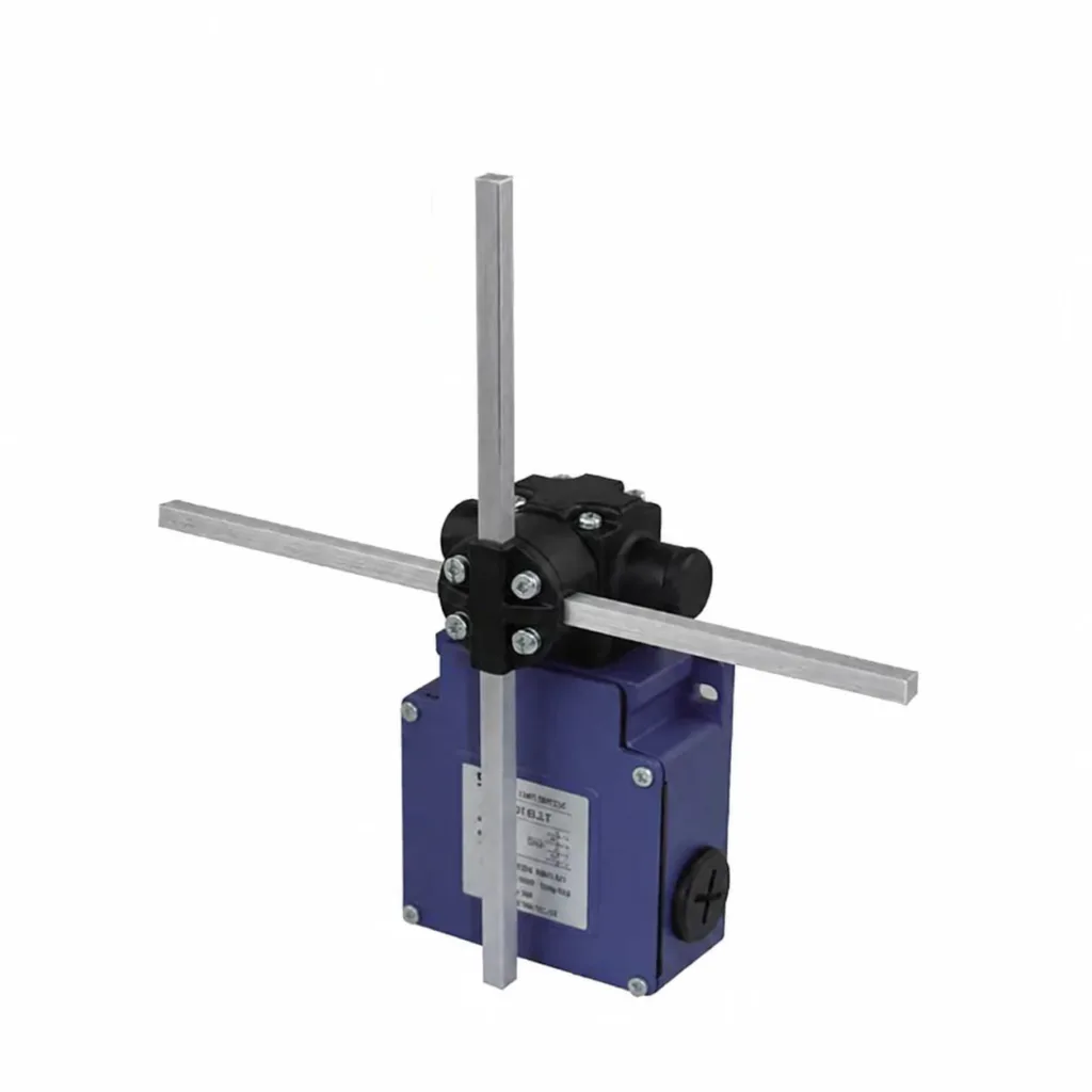
- Geared rotary switches follow mechanism rotation; cross-arm and lever switches are actuated at set positions. The photo shows a cross-arm switch.
- Check mounting, actuator geometry, rotation range or gear ratio, contacts and enclosure. Working and final limits have different duties in the electrical design.
Proximity sensors
Detect a target or measure separation between equipment. A suitable sensor and control arrangement can support crane-to-crane collision avoidance.
Types & matching details
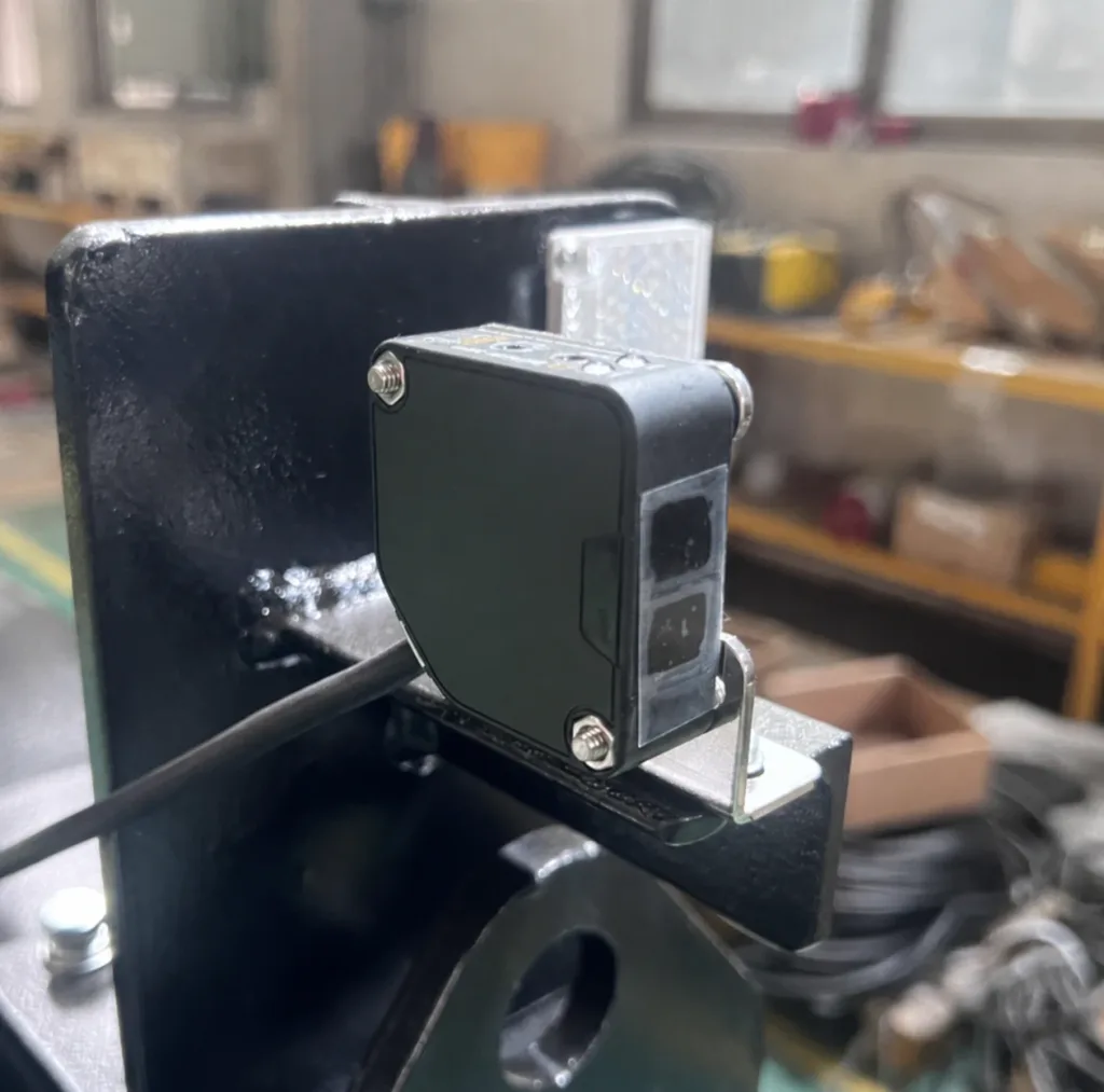
- Photoelectric, distance-measuring and area-scanning devices have different targets and coverage. The photograph shows a bracket-mounted photoelectric device, not a complete protection system.
- Confirm travel direction, speed, stopping distance, alignment, dust and outdoor exposure. General object detection must not be assumed suitable for personnel protection.
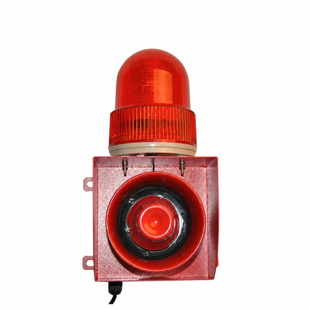
Beacons & sounders
Give a visible or audible indication of crane movement or an alarm condition. Agree what triggers the warning and where it needs to be noticed.
Types & matching details
- Combined light-and-sound units, separate beacons and audible alarms. Select the signal type, supply and mounting for the intended location.
- Background noise, viewing distance, daylight and enclosure protection affect selection. A warning does not detect an obstacle or stop the machine by itself.
Start with the
actual installation.
A replacement on one hoist and a new detection system for shared crane rails need different information.
- 01
Replace a limiter
Identify the sensor and instrument together. Send markings, connections and a photo of the mounting or rope arrangement. Allow for calibration and an installed function check.
- 02
Detect an approach
Describe the cranes, directions, speeds and sensor positions. Detection coverage and the control response must allow for the actual stopping distance.
- 03
Plan for exposure
Rain, dust, sunlight and noise affect selection and mounting. Wind monitoring and storm restraints are separate requirements from travel detection.
See how the crane
is being used.
Operating records can help plan maintenance and investigate recurring alarms. Agree which measurements are available and what the operator or maintenance team needs to see.
01Load readings and operating records
Options depend on the installed sensors and controller. Requirements may include load readings, operating hours, starts or lifting cycles. Define which mechanism each record relates to and how the data will be accessed.
02Condition signals and fault history
Temperature, brake-condition or other measurements need suitable sensors and interfaces. Specify the fault history or trends needed; an existing crane may not already provide those signals.
03Local indication or remote access
A local display, stored event log and remote dashboard are different scopes. Remote access needs compatible equipment, communications and agreed access arrangements. Data reporting does not replace the crane protection circuits.
Need the crane to act on a task?
For positioning assistance or automatic cycles, review the control and automation scope as well as the sensors.
Explore crane automationMatch the hardware.
Confirm the function.
We can review individual replacement devices or a coordinated supply scope. Identify what stays on the crane and what needs to change.
01Can I replace it with a device that looks the same?
Appearance is not enough. Model suffixes can change voltage, contacts, measuring range and output. Send the nameplate, connections and installation photos, plus available drawings.
02Does a weight display provide overload protection?
Only if the selected equipment and control design provide the required limiting function. A display alone shows a reading; it does not establish which crane movement will be inhibited.
03What is included, and what is checked?
Agree whether supply includes the sensor, instrument, brackets, cables and control changes. Confirm the documentation and factory checks for the supplied items. Installed-system checks must verify the actual settings, alarm or stop response and recovery before operation.
Show us the device.
Tell us what it must do.
A clear photo and a short description are enough to start. Add the quantity, destination and required timing.
Discuss safety devices- Crane or hoist details, nameplates, mounting and connection photos.
- Display a reading, issue a warning, limit motion or record operating data.
- Available drawings, supply voltage and indoor/outdoor conditions.