
Lifting Beams & Spreader Systems
Connect the lifting points.
Fit the load.
Lifting beams, spreader beams and multi-point frames for long components, machinery and large modules. Start with the lifting-point layout, load weight and space available below the crane hook.
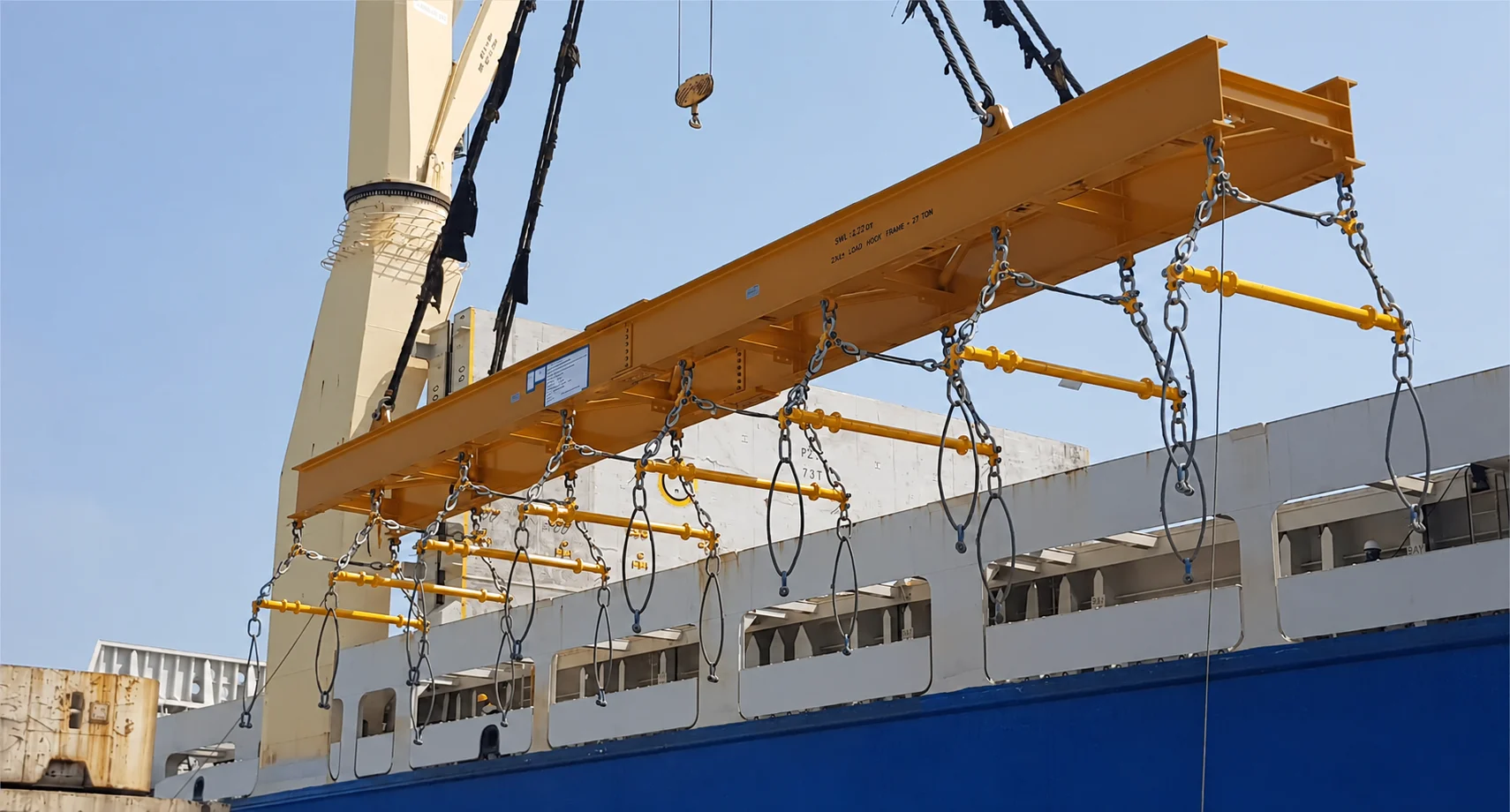
Look at the connections.
Not just the beam.
A lifting beam primarily carries bending; a spreader primarily carries compression from its upper slings. A frame positions connections across a wider footprint. Mixed arrangements also exist.
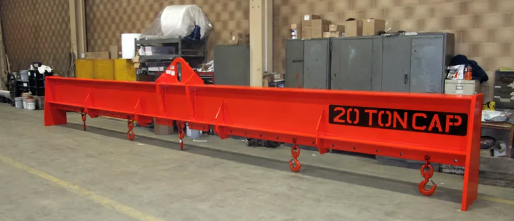
Lifting beams
A central or defined upper lifting point transfers the load to lower connections along the beam.
Applications & selection
- Workshop lifts, machinery and loads with several points along one line. A direct-to-hook arrangement can be useful when upper sling height is limited.
- Check the complete hook-to-load height, beam self-weight and approved lower-point positions. The rating shown in the photo is specific to that beam.
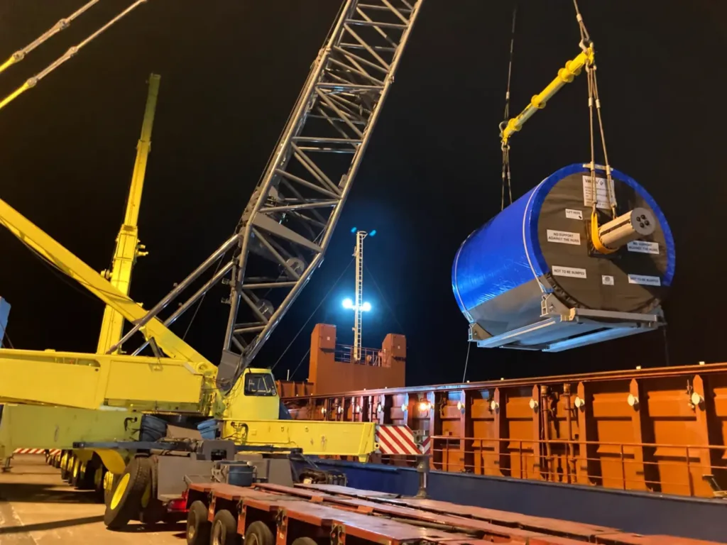
Spreader beams
Upper slings and end connections work together to keep the lower lifting lines separated.
Applications & selection
- Long loads and equipment with separated lifting points. The beam can keep rigging clear of the load where the selected layout permits.
- Available upper-sling height, end-to-end span, sling angles and the rated configuration. Do not assume every span has the same capacity.
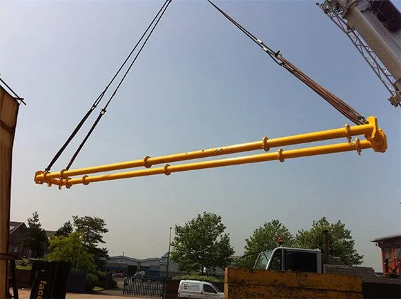
Multi-point frames
Rectangular or other frame layouts position lifting connections across both length and width.
Applications & selection
- Wide machinery, modules and loads with lifting points that are not in one line. Rectangular and triangular layouts serve different footprints.
- Lifting-point coordinates, centre of gravity and load stiffness. Four connections do not automatically carry one quarter of the load each.
One rig.
Several different jobs.
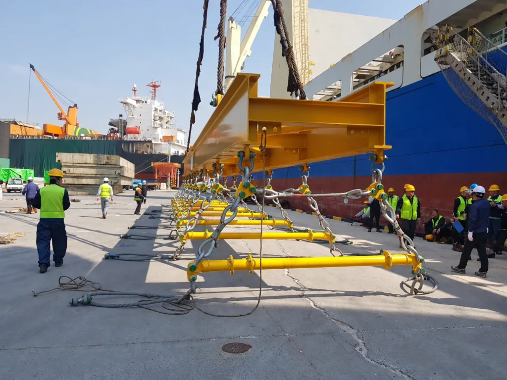
In this unloaded assembly, the large beam carries several short transverse spreaders. Select a point to see how each part connects. This is a specific arrangement, not a universal rigging plan.
Different workpieces.
Different pickup points.
Choose the support and connection layout around the workpiece. The same overall weight can require a very different beam.
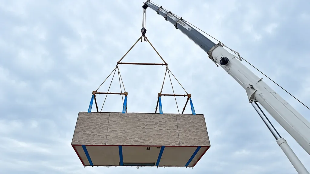
One main spreader. Two lifting frames.
The upper spreader separates two frames along the module. The frames keep the lower slings apart across its width. For a similar load, define the permitted support positions and the height needed for the complete assembly.
- 01
Support the right positions
Define permitted support points, length range and surface protection. A beam still needs suitable slings, hooks or pipe attachments.
- 02
Fit the lifting lugs
Show lug positions and directions, offset weight and clearance at the machine. Include space to connect and remove the rigging.
- 03
Use the full footprint
Coordinate the main beam, transverse spreaders and existing module lifting points. Include both pickup and final placement conditions.
01Roof trusses, long panels or flexible structures?
These may need dedicated support positions to limit deformation, rather than simply a longer beam. Share the workpiece drawing, permitted supports and installation sequence. A specialist truss or panel lifter should be selected for that particular load.
02Magnets, tongs or process hooks beneath the beam?
The beam can position matched attachments, but their contact and operating conditions need separate selection. Magnetic lifting, coil handling and high-temperature process attachments are covered in the wider below-the-hook equipment range.
One repeated load?
Or a changing range?
Choose the adjustment you will actually use. Then define whether the order covers the beam alone or a complete matched assembly.
- 01
Repeat the same layout
For consistent workpieces and lifting-point spacing. Confirm the dimensions and connection directions before manufacture.
- 02
Cover a defined range
Hole positions or sliding connections can suit different loads. Each permitted setting needs its own operating limits and positive retention.
- 03
Change the span
Assemble specified sections and end fittings for different spans. Use the matching configuration chart, hardware and assembly instructions.
01Beam only or ready-to-connect assembly?
List the beam or frame, upper and lower slings, shackles, hooks and any specialist attachments separately. Include a storage stand where needed. If powered adjustment, rotation or load monitoring is required, define controls and power connections as part of the scope.
02Can a beam compensate for an offset centre of gravity?
A suitable arrangement can be designed for it. Provide the centre of gravity and expected load at the lifting points, including any variation between workpieces. Adjustable points do not make an unknown or unbalanced load acceptable by themselves.
03How much headroom is needed?
Measure the available hook-to-load space at the most restricted position. Include upper slings, beam depth, lower rigging and connection access. A direct-to-hook lifting beam may reduce upper-sling height; compare the complete arrangement and its self-weight.
04Can the same beam be used as a spreader?
Only where that exact product and configuration are designed for both uses. Moving the upper connections changes the forces in the beam. A similar appearance or unused lug does not establish an alternative rating.
Specify the material.
Agree the design basis.
Technical information should identify the equipment you are buying: its material, rated configuration, operating limits and the documents included.
- 01
More than a steel grade
Identify grade, thickness and delivery condition for the structure. Share operating temperature and exposure so the connections and protective finish can be specified.
- 02
Tie the rating to the layout
Agree the span or point spacing, working load limit, self-weight and permitted rigging arrangement on the drawing.
- 03
Define what comes with it
Agree material records, inspection and test reports, identification and operating instructions before ordering.
| ISO 17096 | Safety requirements for non-fixed load lifting attachments, including lifting and spreader beams. |
|---|---|
| EN 13155 | Safety requirements for non-fixed load lifting attachments; a reference to establish for the relevant project. |
| ASME BTH-1 + B30.20 | BTH-1 covers design. B30.20 covers marking, construction, inspection, testing, maintenance and operation requirements. |
01Can Q355 and S355 be specified as interchangeable materials?
Do not treat the short grade names as automatic equivalents. Compare the complete material standard and grade, thickness range, delivery condition and required mechanical properties. Material selection also needs to suit fabrication and the operating conditions.
02Which material and manufacturing records should we request?
State any requirement for material inspection documents, such as an agreed EN 10204 document type, and its traceability to the supplied parts. Welding, non-destructive examination and load-test records should be agreed for the particular order. A material certificate is not a complete lifting-device certificate.
Send the lifting points.
And the space around them.
A workpiece drawing and a photo of the pickup location are a useful starting point. Include the smallest and largest loads if one device must cover a range.
Discuss a lifting beam- Weight, dimensions, centre of gravity and lifting-point coordinates and directions.
- Hook or connecting hardware, available height, pickup and landing positions.
- Beam only or complete rigging, adjustment range, environment and project standards.