
Coil, Plate & Long-Load Lifters
Pick up the material.
Protect the product.
C-hooks, coil grabs, plate clamps and purpose-built tongs for steel service centres, processing lines and mills. Choose the attachment around the load shape, pickup position and surfaces it can touch.
Which way does
the coil eye face?
A horizontal bore and an upward-facing bore need different pickup arrangements. Include access around the coil, not just its weight.
C-hooks
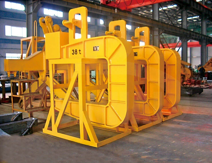
A lower arm enters the coil bore and supports the coil from inside. A counterweight balances the empty hook; no powered opening mechanism is needed.
Applications & selection
- Horizontal-eye coils with clear side access for inserting and withdrawing the arm. Protective pads can be specified for sensitive contact surfaces.
- Coil mass, width and bore diameter determine the arm and balance arrangement. Allow room beside the coil for the complete hook to enter and withdraw.
Telescoping coil grabs
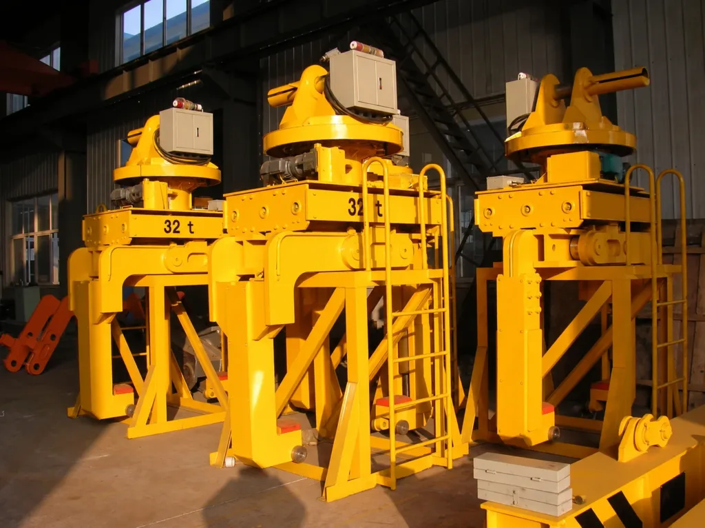
Adjustable legs approach the coil ends; lifting feet enter the bore. Powered opening is useful when coil widths change frequently.
Applications & selection
- Coil width and bore range, outer diameter, nearby coils and the space needed for the legs to descend.
- Specify surface protection, opening controls and any horizontal rotation. A rotator does not by itself turn the coil upright.
Vertical coil lifters
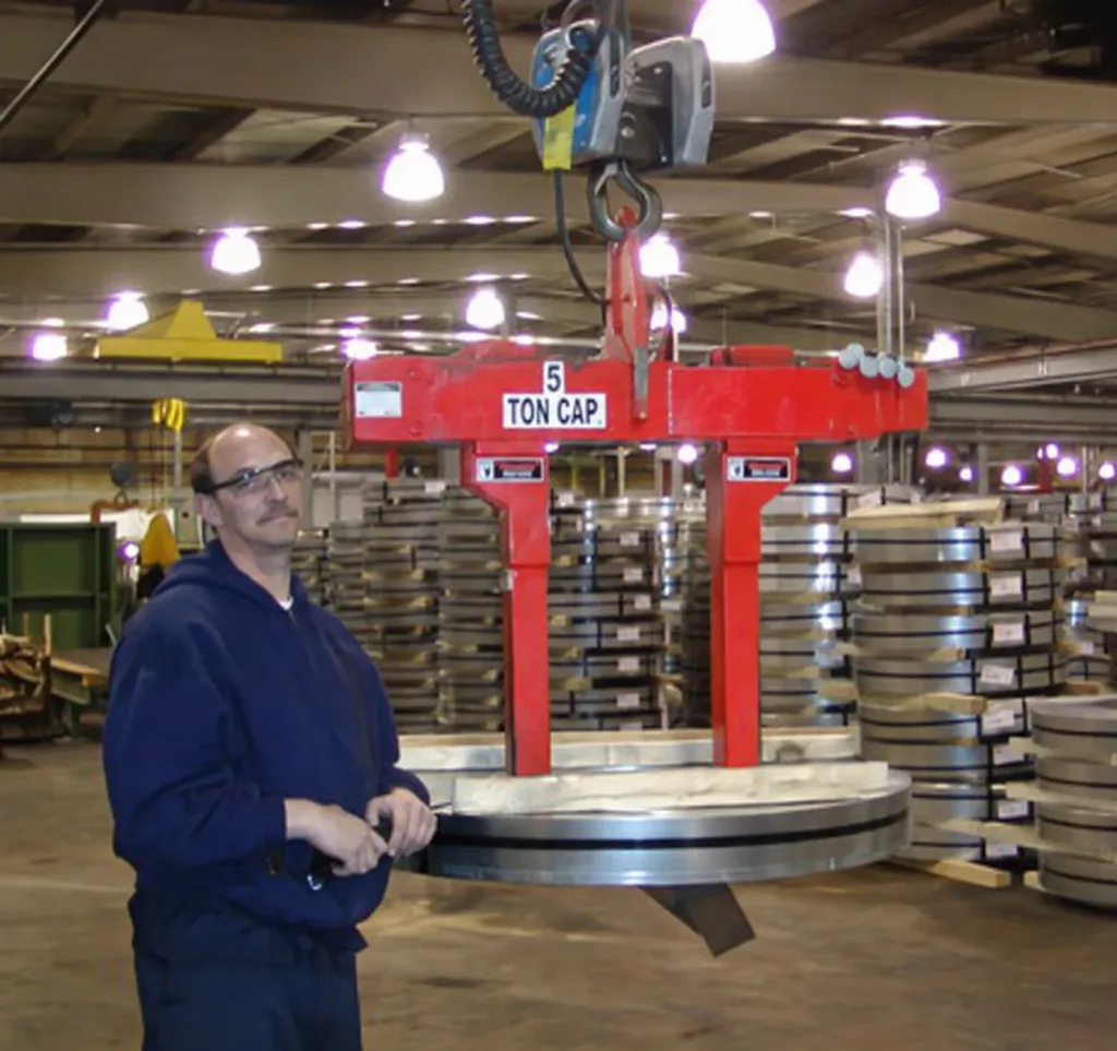
This example lowers its legs into the bore and supports the coil from below. Other vertical lifters use a different contact arrangement.
Applications & selection
- For this bottom-support arrangement, spacers must provide room for the feet to engage and withdraw.
- Provide bore diameter, coil width, packaging and stacking arrangement. Rim grabs and internally gripping designs need their own contact assessment.
01When is a C-hook the better starting point?
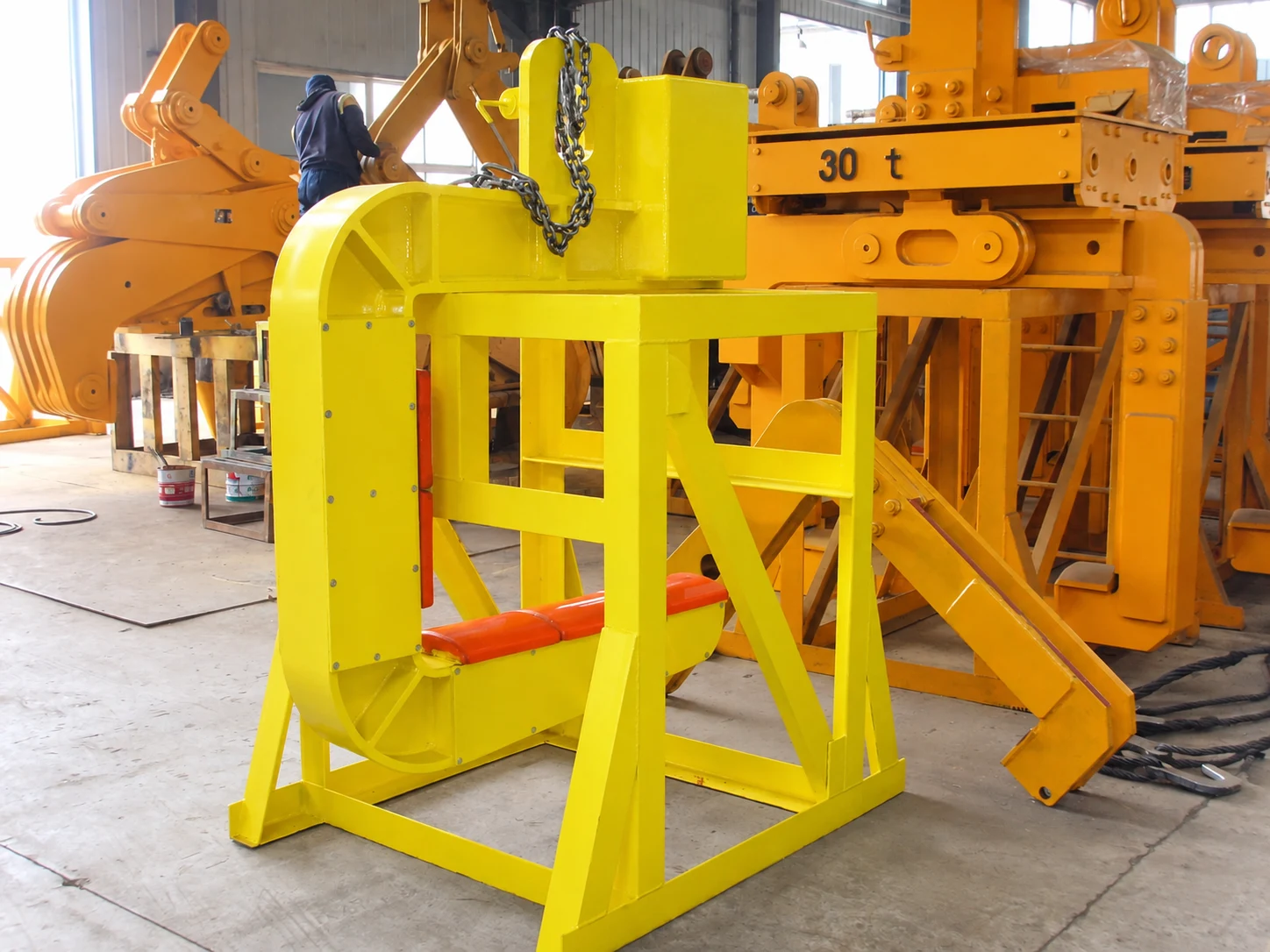
For eye-horizontal coils with clear side access, a C-hook offers a simple support arm through the bore. Match the arm, balance and contact protection to the full load range. The opening photograph shows this arrangement; its marked capacity is not a range for all C-hooks.
02What about narrow slit coils or turning a coil upright?
Narrow coils may need slim legs and special feet to fit between adjacent coils. Changing from eye-horizontal to eye-vertical requires a purpose-designed upending attachment or a separate upender. Specify both starting and finishing positions.
One plate is not
a stack of sheets.
An edge clamp grips an individual plate. A sheet-stack lifter uses carrying arms or forks beneath the load. Choose the pickup method before comparing capacity.
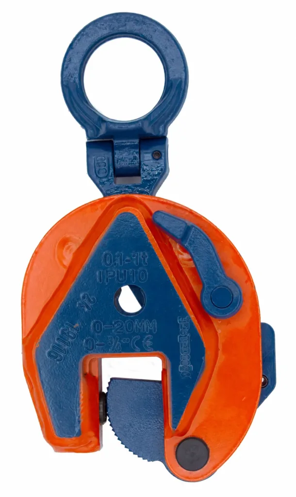
Plate lifting clamps
Select a clamp designed for the lifting direction, plate thickness and surface condition. The photograph shows a vertical plate clamp.
Applications & selection
- Check the selected model’s minimum load, plate hardness, permitted angles and locking instructions. These limits vary by model.
- Toothed contact may leave marks. Tell us whether paint, stainless steel or a finished face must be protected; select a compatible gripping method.
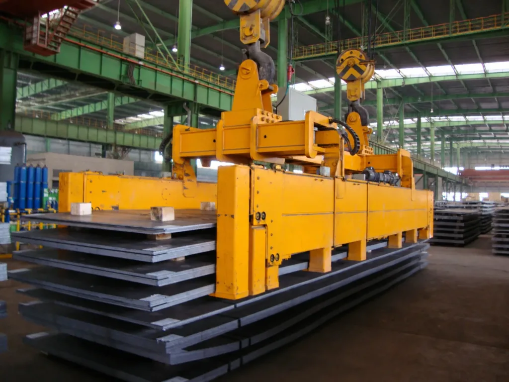
Sheet-stack lifters
Carrying arms support the stack from below. The motorized telescopic arrangement shown uses several support points along the plates; arm spacing and length follow the load.
Applications & selection
- Show spacers, pallet openings and the pickup surface. The carrying arms need a clear route beneath the stack.
- Include shortest and longest sheets, stack height and whether the load is banded or palletised. Packaging must not be assumed to be a lifting point.
01Can one attachment handle single sheets and complete stacks?
Only if the selected design is rated and suitable for both tasks. Thin sheets may need distributed support to control bending. Magnetic or vacuum lifting can be considered separately when the material and surface suit the method.
Fit the contact
to the workpiece.
Pipe, rolled sections and hot billets need different jaws, support positions and contact materials.
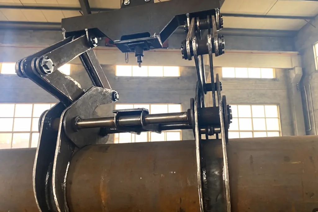
Support the diameter. Check the surface.
The shaped jaws in this example wrap around a cylindrical load. Match the diameter range and contact position to the pipe or bar. For long or thin-walled material, also check wall thickness, bending and the need for separated supports.
- 01
Single piece or bundle?
Show length, diameter, wall thickness and packaging. Several pieces need a support arrangement that retains the complete bundle.
- 02
Shape and temperature
Provide the section and contact temperature. Hot material needs a dedicated design for jaws, pivots and surrounding components.
- 03
Use permitted contacts
Provide roll and neck dimensions, centre of gravity and the handling position. Keep precision working surfaces clear where required.
01Will a lifting beam help with long material?
A beam can separate matched tongs or support points to suit the load. Check the complete assembly, the load at each attachment and the available height; two clamps do not automatically share the weight equally.
Specify what changes
your daily handling.
Choose the contact surfaces, operating method and supporting equipment for the material and frequency of use.
- 01
Jaws, feet & pads
Select replaceable wear parts and protective pads for the surface, temperature and contact loads. Padding alone does not guarantee mark-free lifting.
- 02
Manual or powered
Confirm opening, closing and any rotation separately. Powered units need a defined supply, control interface and load-retention functions.
- 03
Storage & servicing
Include a matched storage stand, access to wear parts and the inspection instructions needed for the selected attachment.
01Which material grades and standards can be specified?
Material grades follow the design of the body, jaws, pins and wear parts. Agree the applicable design and documentation basis for the destination and attachment type, such as EN 13155 or ASME BTH-1 with B30.20. A catalogue photograph does not establish certification for a supplied unit.
02What should be included with the quotation?
Ask for an arrangement drawing, the rated load and size range, attachment self-weight, pickup clearances and supply exclusions. Define required material records, testing and operating documents for the actual equipment.
03Can the attachment work with crane automation?
Powered movement, position sensing and load detection can be specified where the design supports them. Define the crane connection, interlocks, operator controls and recovery sequence. A mechanical automatic latch is not an automated handling system.
Show us the load
and the pickup space.
A workpiece drawing and photographs of the pickup and landing positions give us a useful starting point.
Send the load range.
And the handling task.
Include the lightest and heaviest loads, not only the maximum. Tell us which surfaces may be touched.
Discuss your lifting attachment- Weight range, dimensions, bore or thickness, material, temperature and surface finish.
- Starting and finishing orientation, spacers, neighbouring loads and available hook height.
- Crane hook, operating frequency, power and controls, storage stand and documentation requirements.