
Omnidirectional Transport Platforms
Move sideways.
Keep the load aligned.
Approach a station laterally, shift diagonally or rotate a large assembly. Match the wheel system, load support and controls to the movements your process needs.
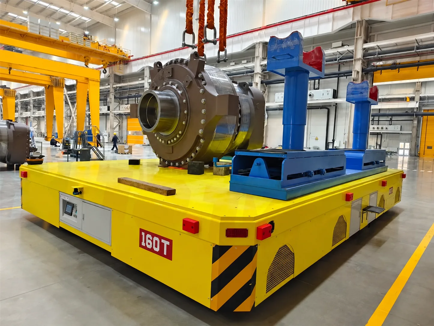
Choose the motion.
Check the space.
Sideways travel and rotation solve different positioning problems. Specify each required mode and check the complete load envelope, including fixtures and overhang.
01Does a cart that turns 360 degrees also move sideways?
Not necessarily. Rotation describes a change of heading; lateral travel is a separate capability. Ask the supplier to demonstrate both with the proposed wheel arrangement and a representative load.
02When is a conventional trackless cart enough?
If the loaded route has room for turns and the station can be approached normally, a conventional steering arrangement may meet the task. Choose omnidirectional movement when sideways approach or retained load orientation has a clear process benefit.
Look below the deck.
Confirm how it steers.
The term omnidirectional covers more than one mechanism. The proposed wheel units, suspension and controls must support the agreed movements on your floor.
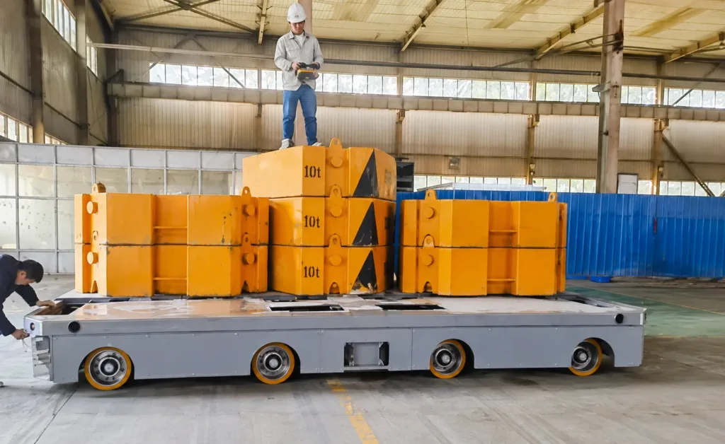
Inspect the running gear.
Exposed wheel assemblies show how many contact points sit beneath the platform. Ask for the actual wheel-unit drawing and load reactions; a photograph alone does not establish the available steering modes.
- 01
Turn the wheel to change direction.
Drive and steering functions work together at coordinated wheel units. Confirm wheel-reorientation time, clearances and whether transitions require the vehicle to stop.
- 02
Confirm the complete mechanism.
Some designs use paired driven wheels within coordinated modules. Request the module arrangement; ordinary differential drive alone does not establish sideways travel.
- 03
Angled rollers provide another approach.
Coordinated wheel rotation can produce translation and rotation using angled peripheral rollers. Compare the proposed system against your wheel loads, surface, joints and maintenance needs.
01Is one wheel system always better for heavy loads?
No universal choice follows from the wheel name. Compare the complete design: supported mass, contact reactions, floor condition, deck height, movement modes and maintenance access. Verify the offered configuration against the site.
Arrive in position.
Support the next operation.
A mobile platform can carry a fixture, but the workpiece still needs defined support and restraint. Agree how it is loaded, aligned and released at each station.
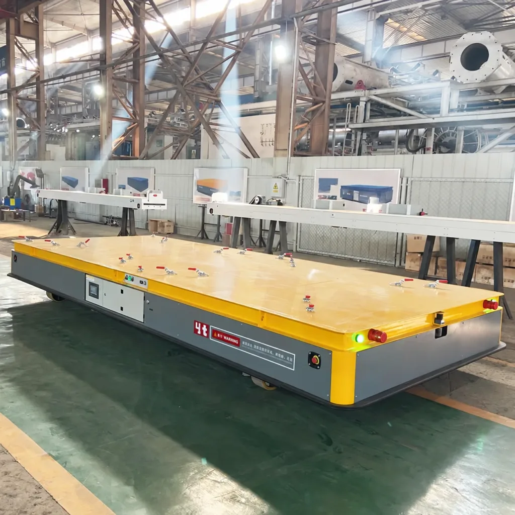
Locate the workpiece on the deck.
A clamped deck suits a defined fixture or workpiece interface. Specify contact points, centre of gravity and access for loading. Identify whether the task is transport, assembly positioning or both.
01What changes for cylindrical workpieces?
A shaped cradle or roller support may be needed. Confirm the diameter range, axial restraint, contact protection and whether controlled workpiece rotation is part of the supplied function.
02Can the platform collect a load from a stand?
A lifting arrangement can be specified with a compatible stand. Agree entry width, lowered height, stroke, support positions and the permitted travel height. A flat transport deck does not provide self-loading by itself.
03What positioning accuracy should I request?
Define the reference point, approach direction, load and acceptable final offset. Separate vehicle arrival accuracy from fixture or mechanical docking accuracy. Agree a repeatable acceptance method instead of adopting a catalogue figure.
04Can two platforms carry one long assembly?
Only with an engineered linked system covering load sharing, steering coordination, stopping and communication loss. Treat the complete assembly and both vehicles as one handling operation; do not assume independent remote-controlled carts can work as a synchronized pair.
The route is more than
an aisle width.
Check wheel reactions and the load envelope at the tightest approach. Include movement-mode changes, stopping and recovery space in the layout.
| Floor and wheel contact | Floor construction, surface finish and assessed capacity; request maximum wheel reactions and contact data with the load and fixtures included. |
|---|---|
| Joints and changes in level | Joint widths, rails, covers, thresholds, damaged areas and local steps, including crossings during lateral travel. |
| Slope and exposure | Gradient and crossfall, indoor/outdoor use, moisture or contamination, and loaded stopping positions. |
| Loaded clearance | Load and fixture outline, door heights, side approach gaps, rotation space, pedestrian crossings and a recovery route. |
01Does zero turning radius mean no clearance is needed?
No. Even when the platform rotates about its centre, the corners of the load sweep an area around it. Include overhang and the agreed protective distance from people, equipment and structures.
02Can the same platform work outdoors or cross uneven floors?
Only within the selected design and assessed route conditions. Supply the actual surface, slope, joints and weather exposure. Wheel material or an outdoor equipment photograph is not proof of suitability for every route.
Choose who controls
each movement.
Remote operation and automatic navigation are separate decisions. Plan how the operator sees the load and how the vehicle responds when movement is interrupted.
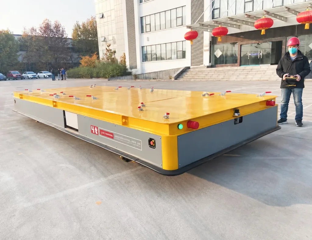
Keep the moving side visible.
The operator position matters when the platform moves sideways or changes heading. Agree directional commands, speed selection and protection around the complete loaded envelope.
01Does omnidirectional mean AGV or autonomous?
No. A platform can provide omnidirectional movement under pendant or radio control. Automatic navigation requires its own sensing, controls, station interfaces and operating-area design.
02What should happen on a stop or lost radio signal?
Agree the defined stopping response, brake behaviour and restart permissions. Assess detection coverage for every required travel direction, load overhang and any fixture that obscures a sensor.
03How do I plan charging and recover a stopped load?
Provide trips per shift, distances, load, positioning time and available charging windows. Request a duty-based battery plan and a documented loaded recovery method, including access, brake release conditions and any towing or lowering equipment.
Specify the package.
Witness the movements.
Agree the vehicle, fixtures, site work and acceptance method before manufacture. Acceptance should reproduce the positioning problem that led you to choose omnidirectional travel.
- 01
List the included functions.
Wheel architecture, steering modes, load support, lift or roller functions, battery, charger, controls and protection. Identify options and maintenance access.
- 02
Prepare the station and route.
Assign the floor assessment, stand or docking interface, charging supply, traffic arrangements, installation and commissioning responsibilities.
- 03
Test the complete operating cycle.
Agree representative load, lateral and diagonal paths, rotation envelope, docking repeatability, stopping and recovery checks. Record the conditions and results.
01Which documents should accompany the platform?
Request the agreed general arrangement and interfaces, wheel-load data, operating and maintenance instructions, electrical information, spare-parts list, test records and applicable destination conformity documents. The required scope belongs in the quotation.
Show the load.
Mark the final position.
Send a load sketch and a marked-up floor plan showing the approach, required heading and destination. Photos of the station and floor help define the next questions.
Discuss your platform- Weight, dimensions, centre of gravity, contact points, fixtures and loading method.
- Lateral or diagonal travel, rotation, target offset, lifting and station handoff.
- Floor and joints, clearances, slopes, trips per shift, control preference and destination.