
Open Winch
Build the lift
around the duty.
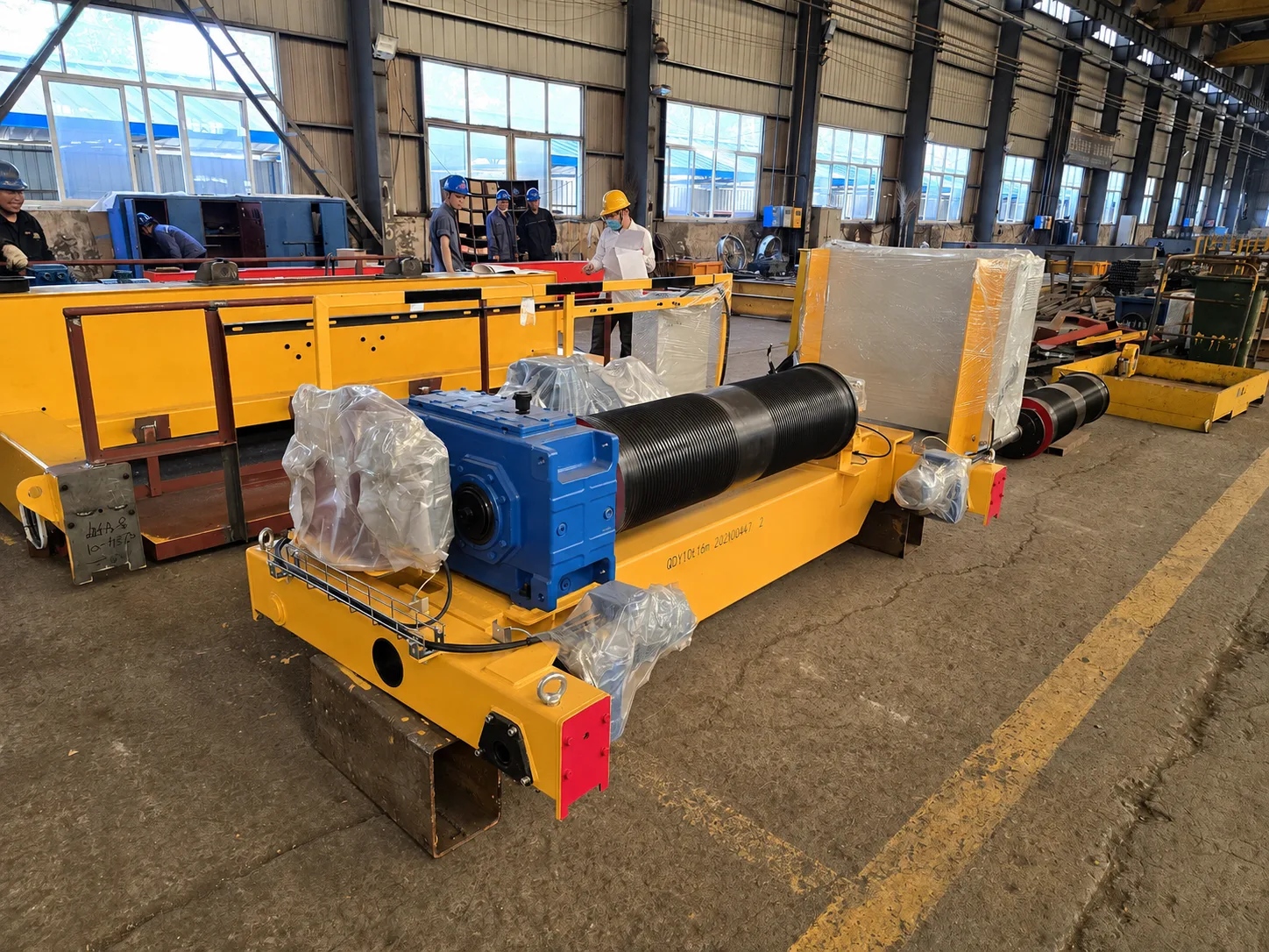
Built-up wire-rope lifting mechanisms for overhead and gantry cranes. Configure the drum, drive and brakes, with trolley travel where required, for the load cycle and installation.
- 01
- 02
- 03
- 04
- 05
When the lifting task
needs a built-up mechanism.
An open winch combines a rope drum, motor, gearbox and braking system on a frame. Define the lifting task and, where a travelling trolley is required, its movement across the crane.
- 01
Suspended load
Include the payload and lifting attachment, normal and maximum loads, and any main or auxiliary hook requirement.
- 02
Operating duty
State the load spectrum, cycles per hour, operating hours and positioning work. Capacity alone does not define the mechanism.
- 03
Available space
Record useful hook travel, upper approach, trolley gauge, obstructions and access for drum, rope, motor and brake maintenance.
- 04
Trolley travel
For a travelling winch trolley, specify travel distance, speed, rail gauge and power feed. Define fixed mounting separately when trolley travel is not required.
One lifting principle.
Different braking arrangements.
Compare the braking architecture alongside load, lift and duty. These are configuration options, not performance grades; each installation needs a complete mechanism review.
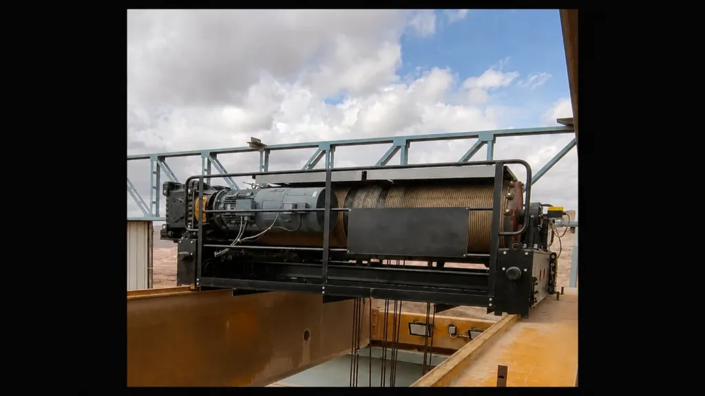
Electromagnetic brake
A hoisting arrangement with electromagnetic braking. Match brake torque, load cycle and thermal duty to the selected drive. Shown in an installed gantry-crane application.
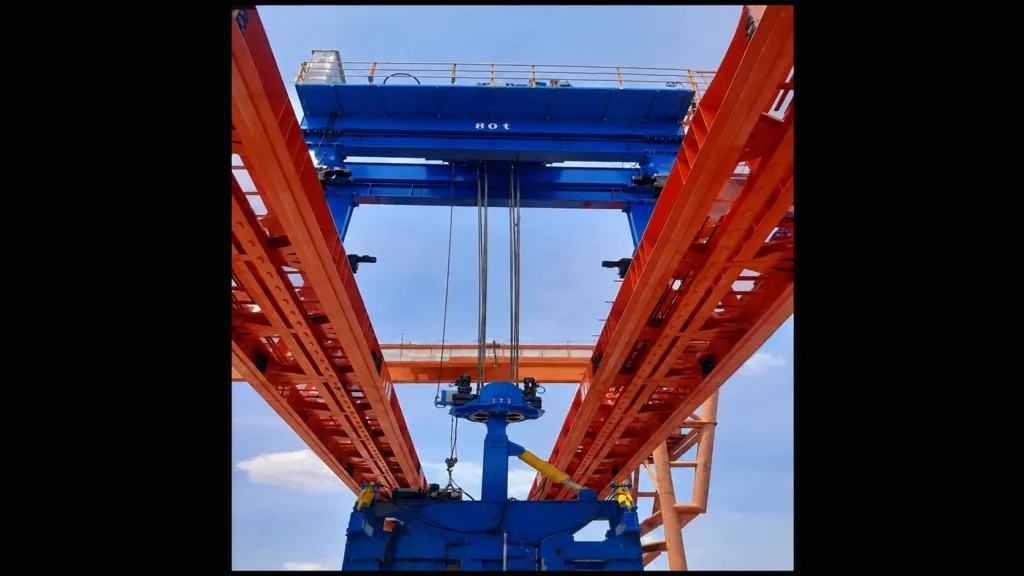
Combined brakes
An electromagnetic brake combined with a hydraulic thruster brake. Confirm brake locations, sequencing and monitoring. Shown in a launching-crane application.
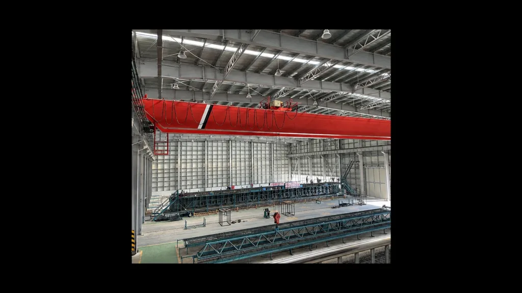
Dual thruster brakes
An arrangement with two hydraulic thruster brakes. Confirm the drive layout, operating duty and service access. Shown in an overhead-crane application.
The unit fits only when
the crane and site fit too.
A trolley gauge or mounting dimension is only the start. Structural reactions, hook geometry, controls and service access all belong in the interface review.
One mechanism.
Several connected design decisions.
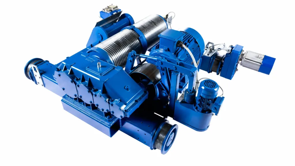
The motor drives the rope drum through the gearbox. The drive and brake operate in a coordinated stopping and holding sequence. Reeving connects drum rotation to hook travel; separate drives provide trolley travel where fitted.
The same capacity can mean
a very different working day.
Explain the load pattern and motion demands so the selected mechanism can be evaluated against the real operation.
- 01
Heavy lifts
A higher proportion of heavy loads changes the fatigue and thermal demands on the drive, brakes, rope and supporting components.
- 02
Long lifts
Greater hook travel changes drum and rope requirements, cycle time and the space needed for the selected reeving arrangement.
- 03
Fine positioning
Inching and repeated starts affect heat management, motor cooling, control tuning and the braking sequence.
- 04
Service access
A compact installation still needs a practical route for inspection, adjustment and component replacement.
A complete proposal has
clear supply boundaries.
Define the mechanism, trolley, controls and site work included in the proposal. Each work package needs an agreed interface and handoff.
Project agreement Supporting steel, rail work, site cabling, installation and commissioning are included only when named in the proposal.
Agree the acceptance basis.
Then check the supplied system.
The inspection and test plan should connect the approved configuration to the actual unit, its interfaces and the required delivery records.
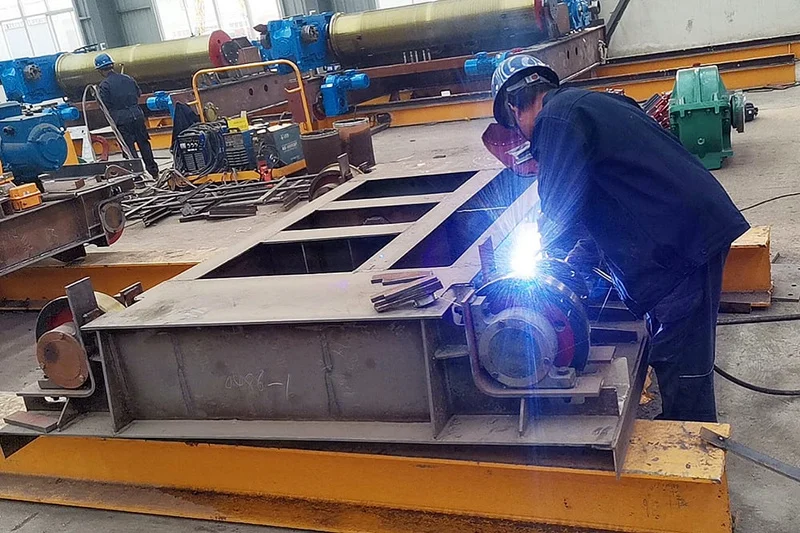
Check the build against the drawings.
Plan material, dimensional, welding and assembly checks around the agreed design. Close the manufacturing records before functional testing and handover.
- 01
Design review
Approve the arrangement, load and duty basis, component schedule, controls, interface drawings and agreed exceptions before manufacture.
- 02
Assembly checks
Inspect identification, assembly, drum and rope path, accessible components, electrical installation and agreed manufacturing records.
- 03
Function tests
Define factory acceptance testing for motion, brakes, limits, protection and controls, with load testing and witness points agreed for the project.
- 04
Handover records
Provide agreed drawings, operation and maintenance information, test records and spare-parts references; define remaining site acceptance tasks.
Start with the operation.
Confirm the specific requirements.
Open winch mechanisms can serve new cranes or replacement projects. Each application needs its own duty and interface review.
- 01
Material transfer
Describe the product, attachment, load pattern and handling sequence for an overhead or gantry crane.
- 02
Assembly work
Identify the required approach, operator visibility and positioning task around machinery or workpieces.
- 03
Crane upgrades
Supply as-built information and a condition assessment so the new unit can be reviewed against existing equipment.
- 04
Process duty
Declare hot loads, corrosive exposure or other process conditions early; equipment suitability must be supported for the selected application.
Resolve the questions
that change the selection.
Use the operating task and verified interfaces to compare proposals on the same basis.
01What is an open winch?
It is a built-up lifting mechanism with a drum, motor, transmission and braking arrangement on a supporting frame. It may be supplied as a hoisting unit or integrated into a travelling crane trolley.
02How is it different from a packaged wire-rope hoist?
Both use wire rope for lifting. A packaged hoist integrates the mechanism into a compact product format; an open winch arrangement offers a different basis for configuring components, duty and interfaces. Select from the actual operating requirements.
03Is this the same as a standalone electric winch?
This page concerns the lifting mechanism within an overhead, gantry or process crane. A standalone pulling or lifting winch has a different mounting and rope-routing boundary and must be selected for its intended task.
04Can a new trolley replace the existing one?
Possibly, after checking the retained crane. Review as-built gauge, rail profile, wheel loads, hook approach, clearances, structural condition, power and control interfaces before confirming compatibility.
05Are dual brakes or special-duty features standard?
They are project-specific configuration decisions. The brake arrangement, monitoring, environmental protection and supporting evidence must be confirmed for the selected equipment and application.
06What information is needed for a quotation?
Send load and attachment details, lift height, operating cycle, speeds, drawings, trolley or support dimensions, power supply, environment, destination and required supply scope. Existing-equipment photos are useful for replacement projects.
Send the duty and drawings.
We help define the unit.
Start with the information you have. We will identify the remaining selection and interface decisions before preparing the equipment scope.
Request winch review- Normal and maximum loads, lifting device, main or auxiliary hook
- Useful hook travel, speeds, positioning and operating modes
- Load spectrum, cycles per hour, running time and shifts
- Gauge, rails, support drawings, hook approaches and service access
- Supply, controls, heat, dust, weather and process conditions
- Location, required documents, site work and delivery boundary