
Trackless Transfer Carts
Heavy loads.
Flexible routes.
Move dies, coils and equipment between workstations without laying rails. Choose the load support and steering around your floor, aisle layout and working shift.
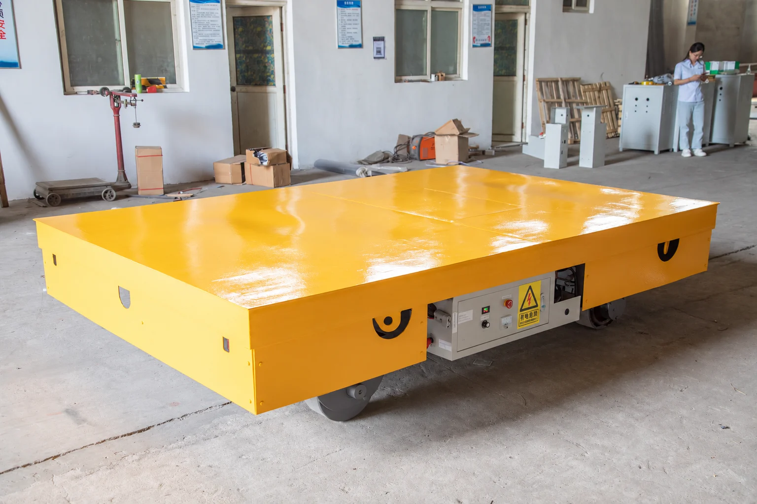
Start with the load.
Then shape the deck.
These equipment examples show different support needs. Select the vehicle around the complete load and its handling method.
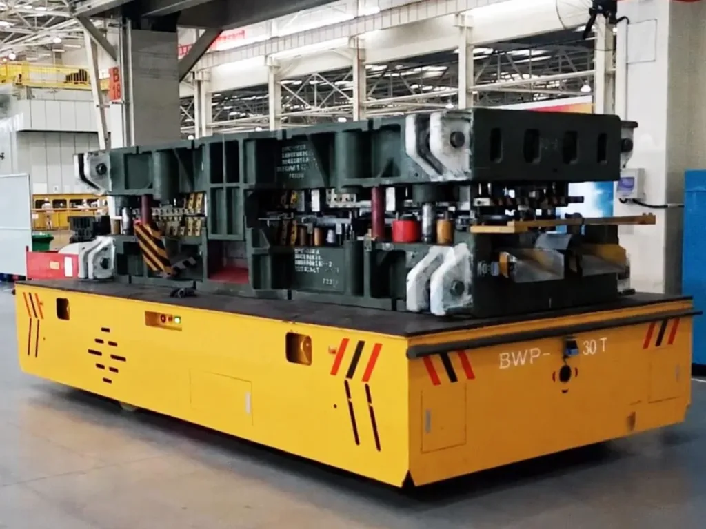
Support the contact points.
Give the die footprint, weight and loading method. Local loads on feet or runners matter as much as the total payload.
Selection details
- Confirm deck height, clear approach space and how the die crosses to the press. A flat cart alone does not provide a die-change mechanism.
- Define support points, centre of gravity and restraint. Include fixtures in the transported weight.
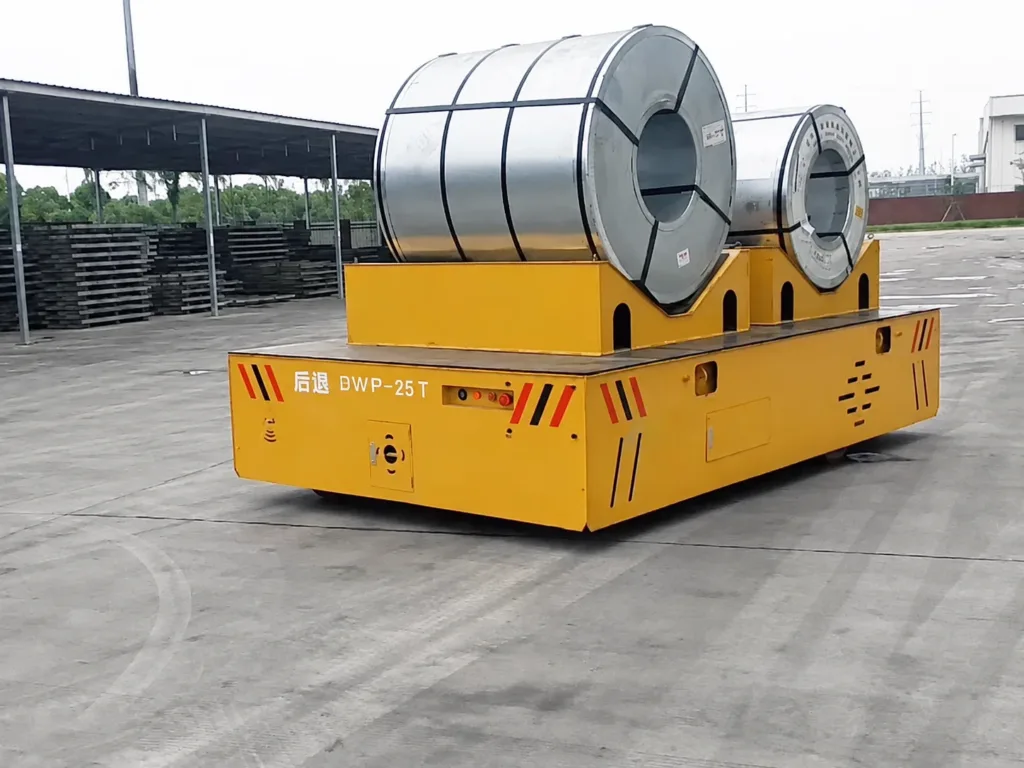
Match the saddle to the coil.
A shaped support holds a cylindrical load in position. Specify coil diameter, width, orientation and surface protection.
Selection details
- Allow space for the crane attachment to place and release the coil. Packaging bands are not a substitute for load restraint.
- Check stability while turning, braking and crossing changes in level. The support must suit the complete coil range.
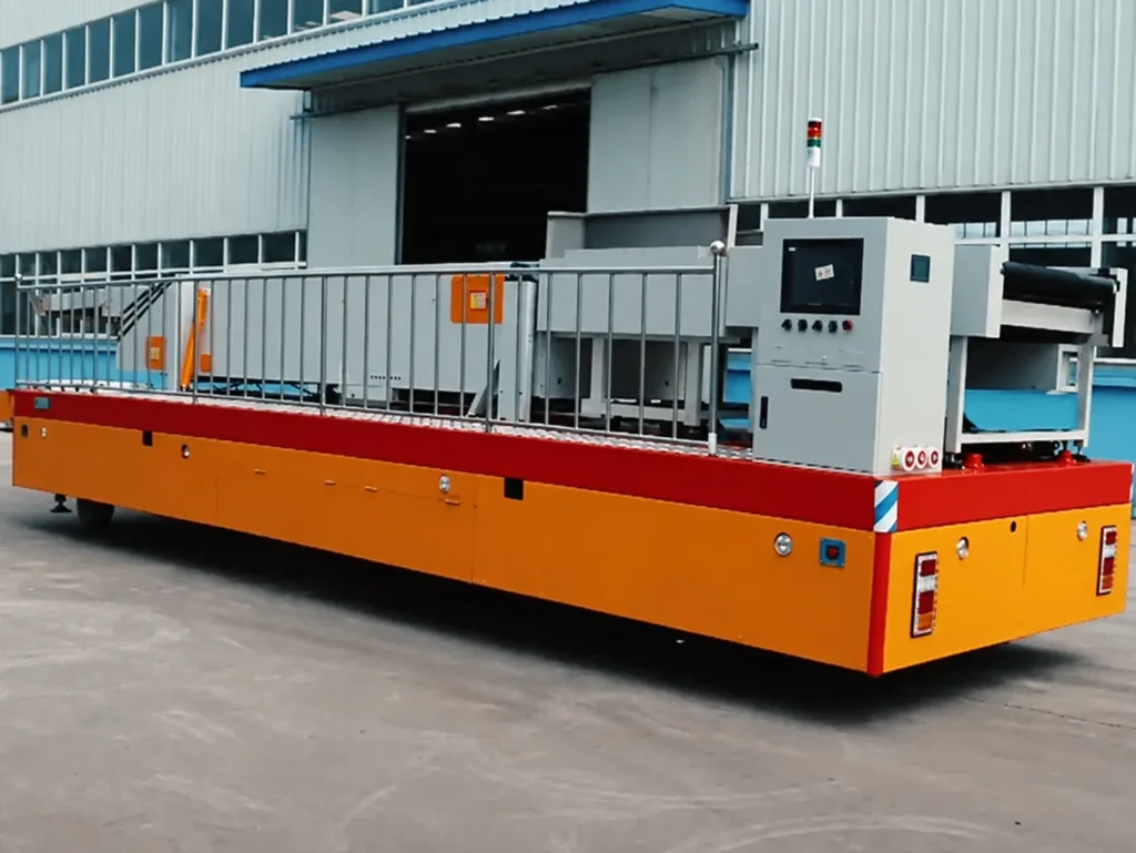
Plan the loaded envelope.
Large assemblies can extend beyond the deck. Check overhang, service connections and access at both loading points.
Selection details
- Identify the lifting or jacking points and any dedicated fixture. State how the assembly is secured to the platform.
- Confirm door clearance, final position and unloading access. Photograph the tightest approach, not just the open travel aisle.
How does the load
get on and off?
Flat decks and saddles need an external loading method. Add a lifting or transfer function when the station needs it; these options can combine with different steering and control systems.
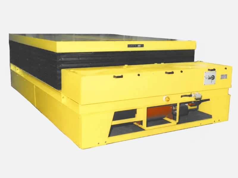
Match the station height.
A powered deck raises the supported load to an agreed working level. Specify the lowered height, stroke and load distribution.
Interface details
- Confirm whether travel is allowed with the deck raised, and at what load and height. Agree protection around moving parts.
- A lift aligns heights; it does not itself push a die into a press. Rollers, push-pull equipment and retention need a separate interface design.
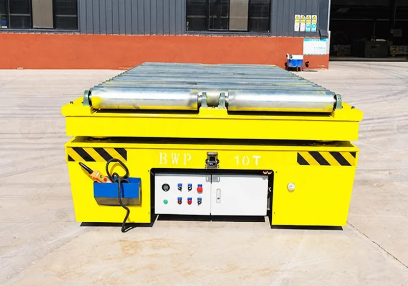
Bridge two handling stations.
Powered rollers can move a suitable load base between the cart and a conveyor or machine. Match direction, roller spacing and the underside of the load.
Interface details
- Agree docking, level alignment, gap support and load stops. Define the permission sequence before either conveyor moves.
- A roller deck may also lift. Specify travel, lift and conveyor functions separately, including how the load is retained during vehicle movement.
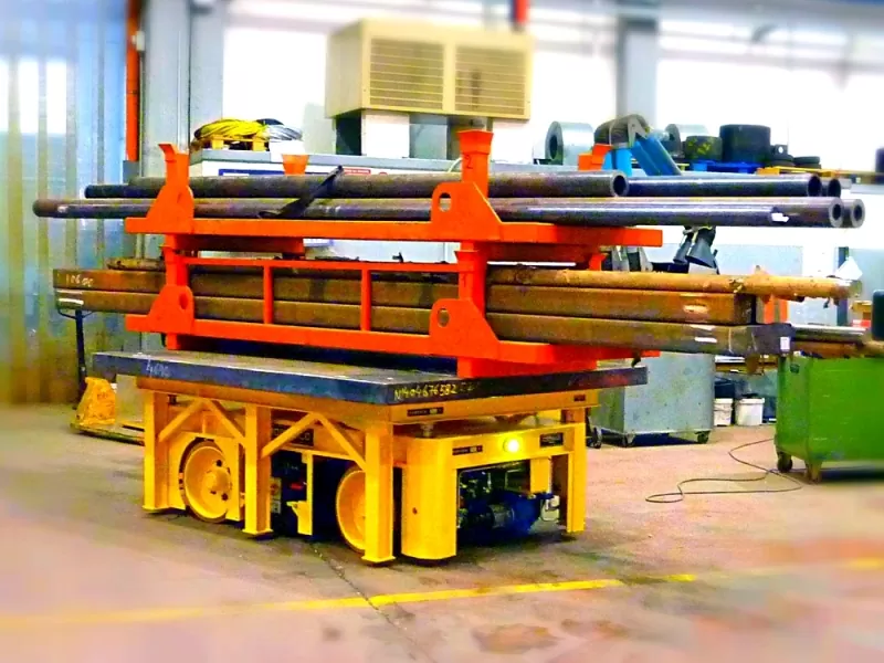
Enter below. Lift. Set down.
A low platform can collect a load on a purpose-made stand, leaving the stand at the destination after lowering. The stand and vehicle must be designed together.
Interface details
- Provide entry width, underside clearance, support spacing and the fully loaded deflection. Check clearance throughout lifting and withdrawal.
- Define the contact and lifting points, stability and load restraint. Do not assume an ordinary warehouse pallet is suitable for a heavy industrial load.
Check the whole turn.
Including the load.
Trackless describes the running surface. The wheel and steering arrangement determines which movements the cart can make.
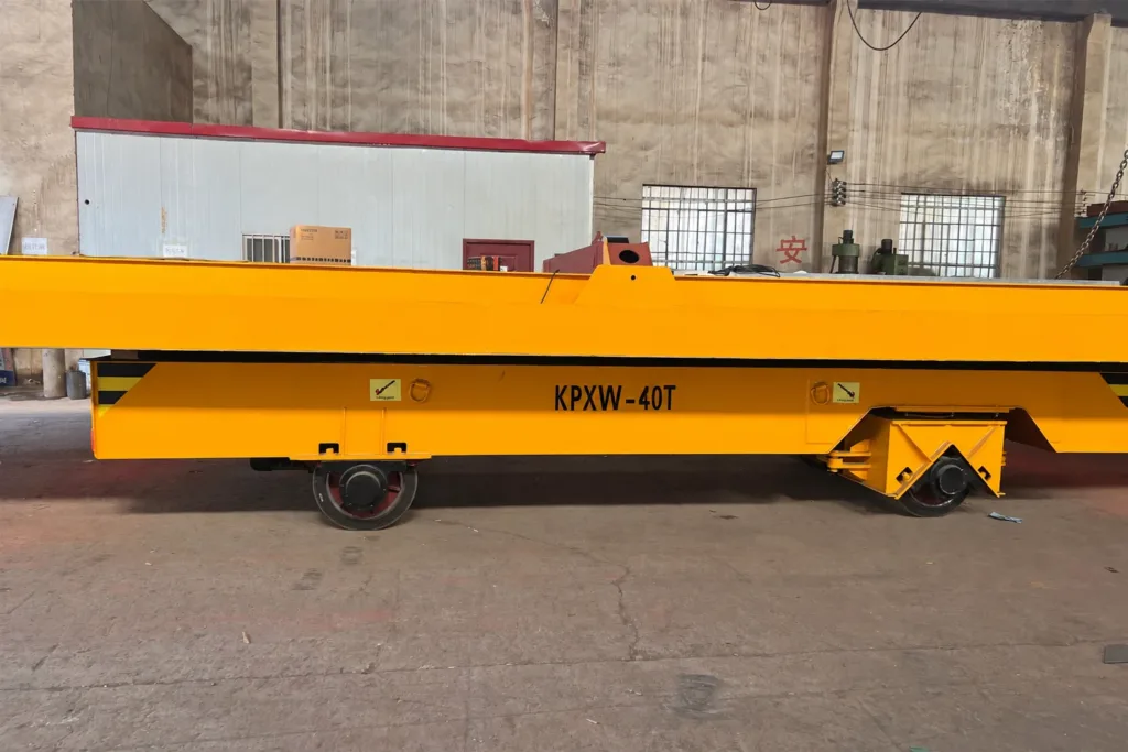
Look below the deck.
Wheel assemblies, wheelbase and steering geometry affect the route the platform follows. This side view shows floor-contact wheels; confirm the available steering modes on the proposed design.
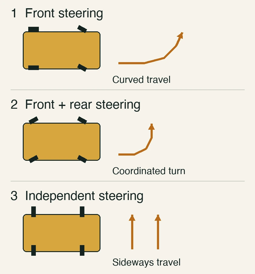
A turn and a sideways move need different steering.
Front steering follows a curve. Coordinated front and rear steering can reduce the turn space for a given layout. Independent wheel steering can add lateral movement. Arrows illustrate movement only; the supplier must provide the loaded swept path.
01Does every trackless cart rotate on the spot?
No. Some designs turn while travelling; other configurations can rotate or translate sideways. Ask for the motion diagram and a loaded route demonstration. Even a cart that rotates about its centre needs clearance for the corners of its load.
The floor carries
the wheel loads.
A clear route is only the start. Check the floor structure and surface against the proposed vehicle, with its load and fixtures included.
| Floor structure | Slab drawings or assessed capacity, joints, covers and local damage. Request maximum wheel loads from the vehicle supplier. |
|---|---|
| Surface and transitions | Surface finish, contamination, steps, thresholds, gaps and changes in level along the full route. |
| Gradient and weather | Steepest slope and crossfall, indoor/outdoor sections, rain or standing water, and stopping positions. |
| Loaded clearance | Door widths and heights, corners, overhang, pedestrian crossings and room to stop or recover the cart. |
01Can a workshop cart run outside or climb a ramp?
Only if the selected design and site assessment cover those conditions. Share the gradient, surface grip, drainage and loaded stopping locations. An outdoor photograph is not proof of all-weather or ramp capability.
02What about hot loads, hazardous areas or very long assemblies?
Identify load and ambient temperatures, exposure time, the site hazardous-area requirements, and the complete load dimensions. Heat protection, suitable electrical equipment, multi-axle layouts or synchronized vehicles require a specific design and acceptance scope. These are not standard capabilities of every trackless cart.
03Will the wheels damage the floor?
Wheel material alone cannot answer this. Wheel loads, contact area, floor finish, debris and steering movement all matter. Ask the supplier to confirm the wheel selection against the site conditions; do not assume that rubber or polyurethane guarantees a mark-free floor.
Plan the trips.
Plan the recharge.
Battery capacity should follow the actual duty: loaded and empty travel, starts, gradients and any powered deck functions.
- 01
Define the working cycle
Provide route length, trips per shift, load pattern and available charging breaks. Confirm charger input, battery care and replacement access.
- 02
Keep the route in view
Choose pendant, radio or an operator platform around visibility, travel distance and the walking route. Agree crossings, stopping arrangements, warning devices and emergency-stop access.
- 03
Agree each station interface
Match the deck to the loading equipment. Powered lifting or roller functions need their own load support, alignment and movement permissions.
01Does remote control make the cart an AGV?
No. A radio remote lets an operator command movement. Automatic operation requires a defined navigation and station system, protective functions, interfaces and recovery procedure. State that need separately from the steering choice.
02When should I consider rail, AGV or a trailer?
A fixed repeat route may suit rail transfer. Sideways positioning needs a specified multidirectional arrangement. Unattended operation needs an AGV system. A towable trailer needs a separate towing vehicle and does not provide its own drive. Start with the route and station task, then choose the appropriate system.
03How many hours can it work on one charge?
That depends on the agreed working cycle, battery, load and site. Request a duty-based estimate with its assumptions and charging plan, rather than comparing catalogue hours measured under different conditions.
Define the package.
Prove it on your route.
Agree the vehicle configuration, site responsibilities and acceptance checks before manufacture.
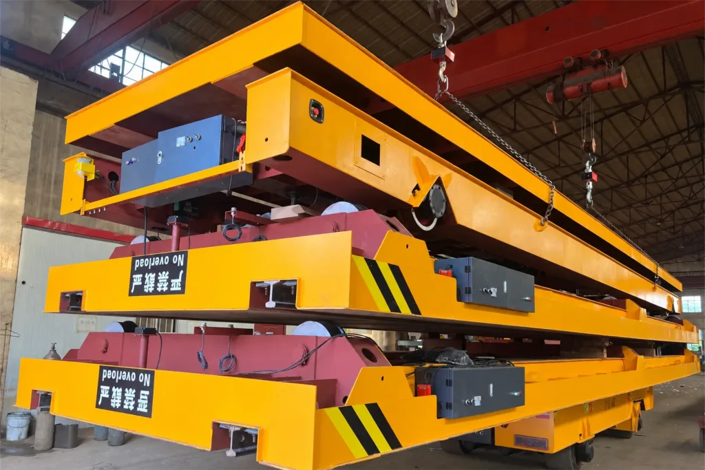
Specify the equipment included.
The frame, wheel assemblies, power equipment and controls form a package. Identify the charger, fixtures, spare parts and documentation in the quotation and agree who supplies each item.
- 01
Confirm what arrives
Deck or load fixture, wheels, steering, drive, brakes, battery, charger and controls. List options separately and agree access for maintenance.
- 02
Prepare the working area
Assign floor assessment and repairs, charging provision, loading equipment, traffic arrangements and commissioning support.
- 03
Test the agreed operation
Agree load, steering, stopping, emergency-stop and charging checks. Include station trials where fitted, operator instruction and maintenance records.
01Which documents and certificates are included?
Specify the destination and required documents in the enquiry. Request the agreed drawings, operating and maintenance instructions, test records and applicable conformity documentation. Materials and certification depend on the chosen design and contract.
Send the load.
Sketch the route.
A marked-up layout and photographs of the load, tightest turn and floor transitions are enough to start the discussion.
Discuss a trackless cart- Weight, dimensions, centre of gravity, contact points, loading method and required fixture.
- Distances, aisle and door sizes, turns, floor condition, gradients and indoor/outdoor sections.
- Trips per shift, control mode, charging provision, station functions, destination and supply scope.