
Heavy-Duty & Special Transporters
Heavy loads.
Moving at ground level.
Move tooling, large fabrications and ship sections at ground level. Compare electric platforms, multi-axle elevating vehicles and modular transporters around the load, loading method and working route.
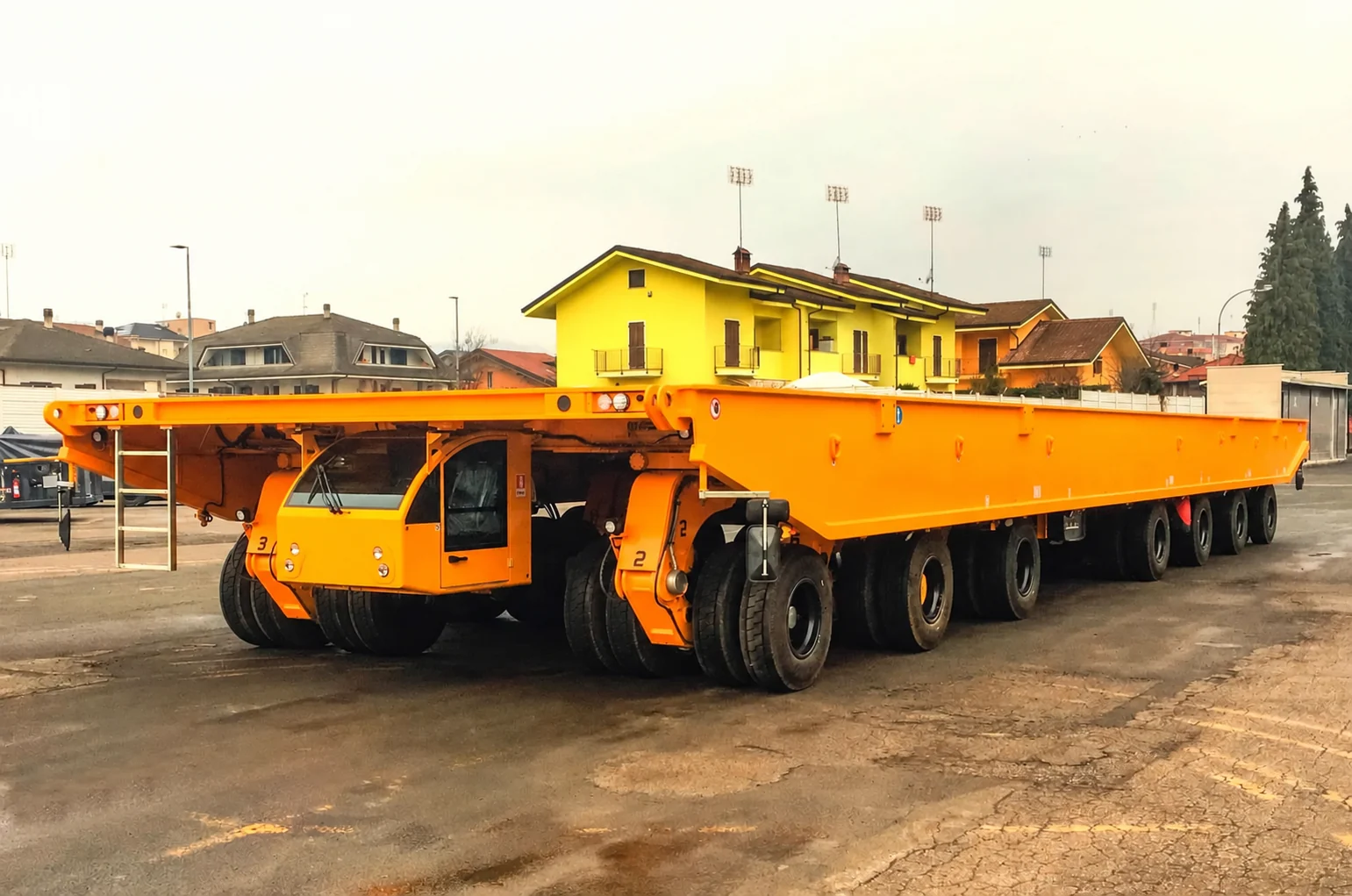
Start with the load.
Then choose the vehicle.
Low-platform carts, cab-equipped trucks and multi-axle elevating vehicles serve different handling needs. A simple-looking flat cart can carry heavy loads. Electric drive, hydraulic steering and lifting are configuration choices that can be combined.
Explore trackless transfer carts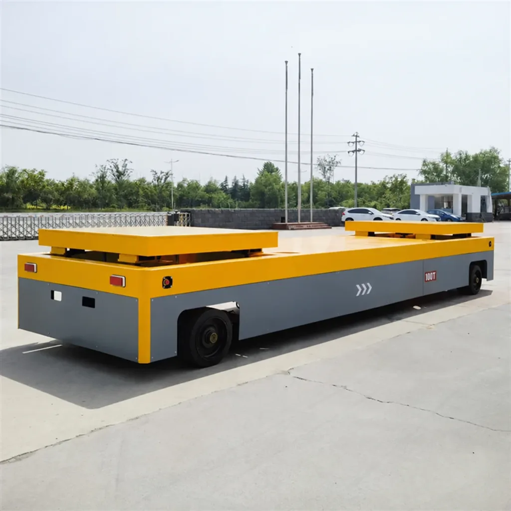
Heavy loads on a low deck.
A reinforced box-section chassis and rated wheel assemblies carry heavy dies, machinery and workpieces in a familiar flat-cart form. Deck supports, wheel loads and floor capacity determine suitability. Local lifting pads can be added for load transfer.
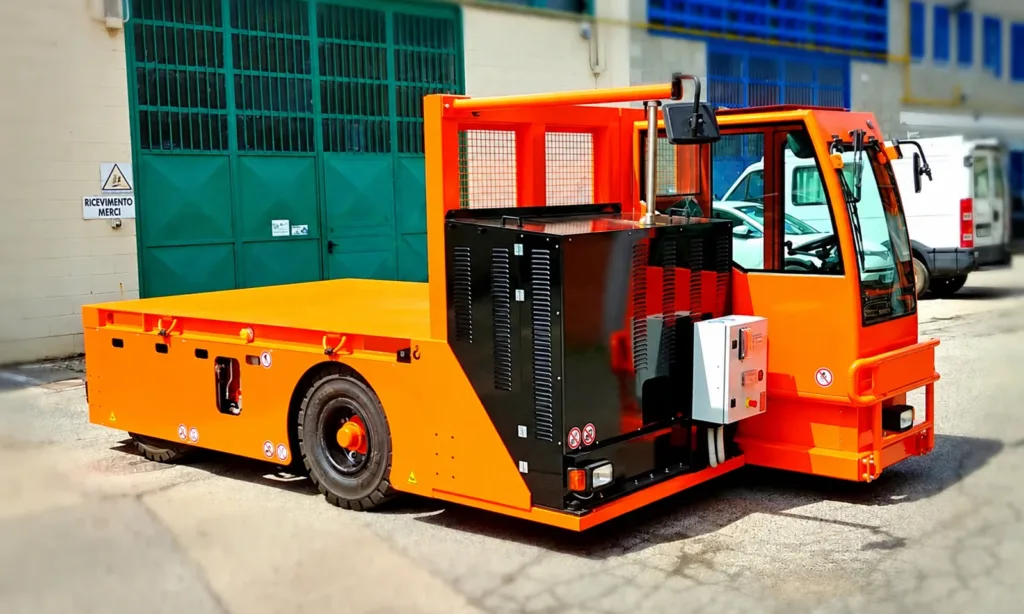
Carry tooling and heavy components.
Electric traction moves the vehicle between production areas. A fixed deck receives loads from a crane or handling station; a lifting deck can be specified when the transfer needs it. Plan charging around the shift and route.
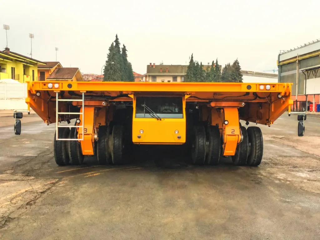
Pick up large supported structures.
A deep frame spreads the load across multiple wheel units. Hydraulic suspension shares axle loads and provides platform height adjustment for pickup and set-down. This arrangement suits large fabrications and ship sections.
Pick up a supported load.
Set it down at the next station.
On an elevating transporter, lower the platform beneath the load supports, raise it to take the weight, then travel at the specified transport height. Lower onto receiving supports at the destination. Keep part of the suspension travel available for route unevenness.
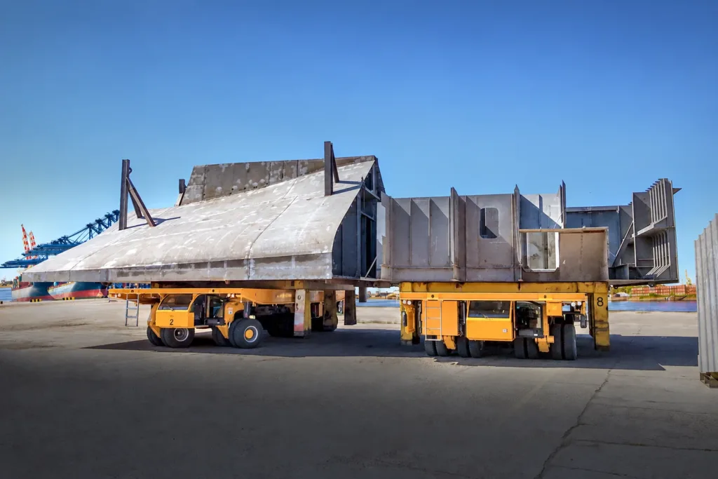
Coordinate two platforms beneath one load.
A single platform can carry a fabrication within its support envelope. A coordinated pair extends that footprint for a wide ship section. Steering, lifting, load sharing and stopping must work together across both vehicles.
Fit the platform
to what it carries.
Special transporters are defined by their load interface: a flat deck for slabs, a saddle for coils, locating supports for dies, or a container cradle for scrap. These fittings can be combined with different drive and chassis arrangements.
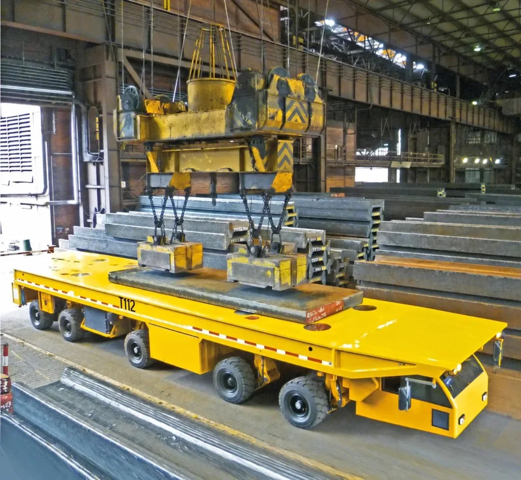
Slab and plate transfer.
A multi-axle deck transporter receives steel from the overhead crane and carries it between storage and production areas. Loading space and cab position are arranged around the mill workflow.
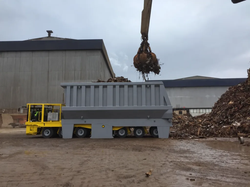
Dedicated scrap-container transport.
A purpose-built carrier supports a high-sided scrap container beneath the loading equipment. Container supports, operator visibility and protection from debris shape the vehicle arrangement.
Change the footprint.
Combine the axle units.
An SPMT combines powered axle modules to support loads that vary greatly in length, width or mass. It is a different chassis strategy from a fixed-size plant transporter; modules, power units and load supports are planned as one transport arrangement.
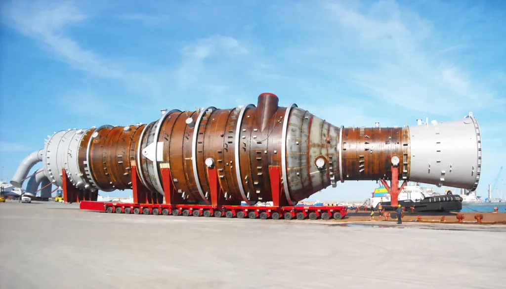
One load. A modular footprint.
Connected axle units support a large process vessel. Choose modular transport for changing project loads; consider a fixed platform for repeated moves within a consistent load envelope. Define support reactions and route limits before configuring the modules.
Follow the route.
Align with the load station.
Coordinated wheel steering guides the loaded platform through the yard. Select the required modes and cab or remote control to suit the route and operator visibility.
Explore omnidirectional positioning- 01
Travel between workshops.
Wheel groups follow a common turning path for travel between workshops and storage areas.
- 02
Approach from the side.
Wheel groups steer in parallel for a diagonal or lateral approach, where the selected wheel geometry permits it.
- 03
Turn within the working area.
Wheel groups turn around a shared centre to change the platform heading within the available swept area.
Size the vehicle
for the actual move.
Choose energy supply, traction, load transfer and controls separately. Battery, diesel or hybrid power does not by itself define the steering, lifting or automation capabilities.
| Payload & deck | Total transport mass, centre of gravity, support positions and deck dimensions. |
|---|---|
| Axles & tyres | Number and spacing of wheel units, tyre selection and maximum ground reactions. |
| Load transfer | Fixed deck loaded by crane, or elevating deck with defined pickup stroke, transport height and receiving supports. |
| Energy & traction | Battery charging opportunities, diesel operating constraints or hybrid duty; electric or hydrostatic traction matched to the operating cycle. |
| Steering & control | Required turning paths, clearances, cab or remote operation; automatic guidance specified separately when needed. |
| Operating environment | Gradient, crossfall, surface condition, clearances, heat exposure and weather protection. |
| Delivery scope | Load-support fittings, drawings, commissioning, training, maintenance information and agreed acceptance tests. |
01How does a heavy platform transporter differ from an SPMT?
A heavy platform transporter uses a chassis with a defined deck size and axle arrangement. An SPMT uses modular axle units that can be combined for different load footprints. The load size, transport frequency and need to change configurations guide the choice.
02What determines the rated payload?
Payload depends on the complete configuration: chassis, support positions, axle and tyre loads, centre of gravity, operating speed and route. The quotation identifies the rated load and operating limits for the selected arrangement.
Tell us what moves.
Show us where.
Send the load drawing and a marked route. We can then define the platform, running gear and loading method for the job.
Discuss your transporter- Transport weight, dimensions, centre of gravity and bearing points.
- Pickup and set-down method, support heights and single or paired operation.
- Surface capacity, slopes, clearances, travel distance and trips per shift.