
01 · SOLUTIONS / OPERATING CONTEXTS
The load is only
the start.
Material handling becomes a production issue when a load crosses a process boundary: receiving into storage, storage into a machine, a hall into a yard, or packing into dispatch. Start with the route. Define the lifting and transfer roles around it.
- 01
- 02
- 03
- 04
Start with the operation.
Then define the handling roles.
The product name is not the starting point. The material, hand-offs, operating pressures and system boundary determine which equipment and engineering support belong in the discussion.
- 01
The real material.
Define the load form, condition, attachment and any change between receiving and dispatch.
- 02
Every hand-off.
Mark where the load waits, changes equipment, crosses traffic or enters another process zone.
- 03
The operating pressure.
Heat, cold, dust, wind, hygiene, timing, access and redundancy can change the handling concept.
- 04
The system role.
Separate equipment, structure, controls, interfaces, recovery and acceptance before defining supply scope.
Where does the flow
break down?
Each industry has its own material, timing, access and hand-off conditions. Select one to inspect the process moments that define the handling discussion.
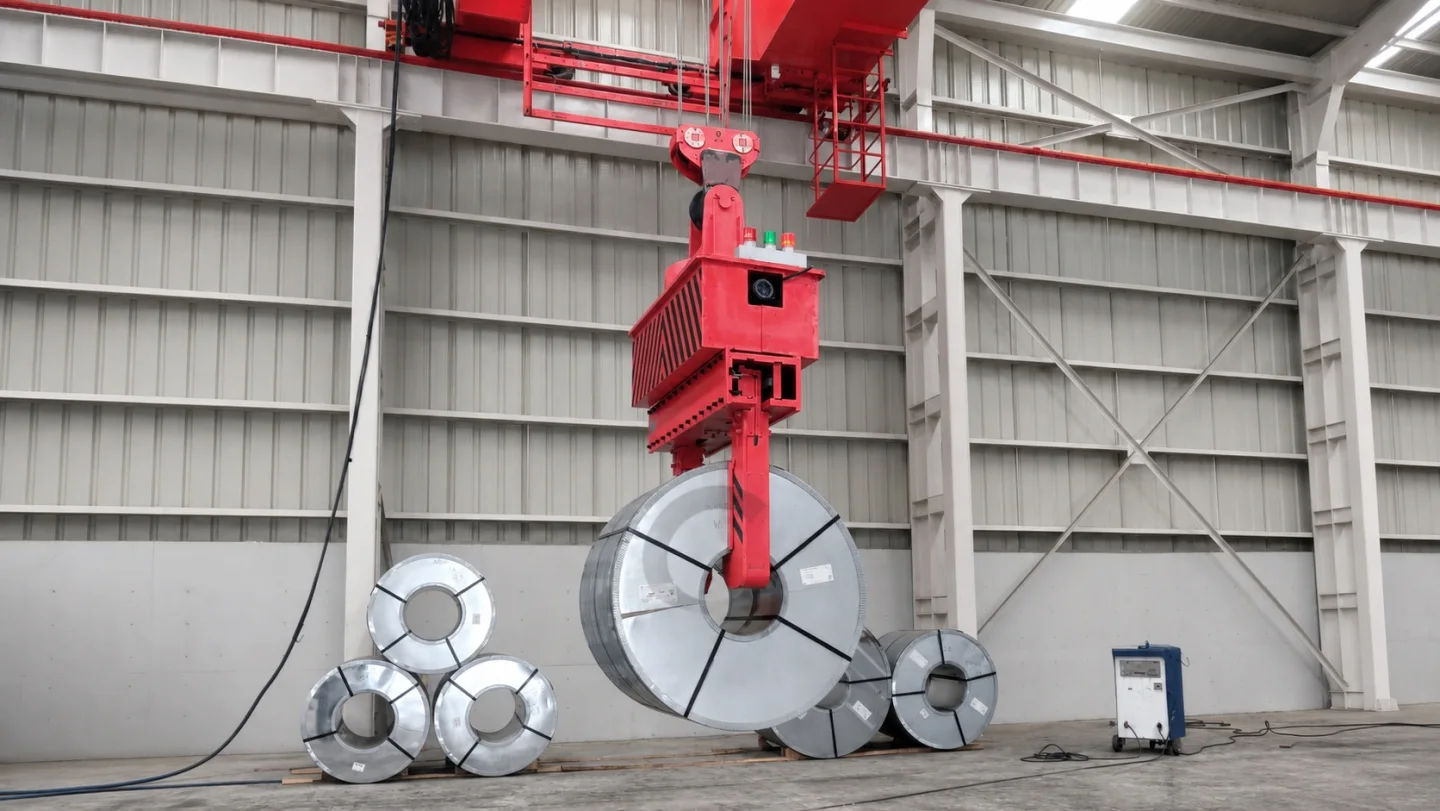
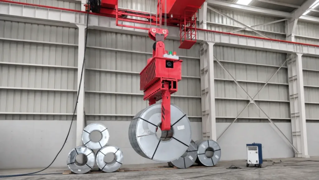 Steel Mills & Metal ProcessingReceiving, processing, inter-bay transfer and dispatch all change how coils, plate and long products should move.
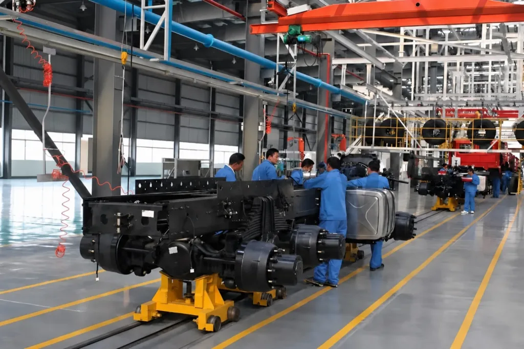 Automotive & Assembly ManufacturingTool readiness, line-side presentation, inter-zone hand-offs and maintenance access decide whether flow keeps pace.
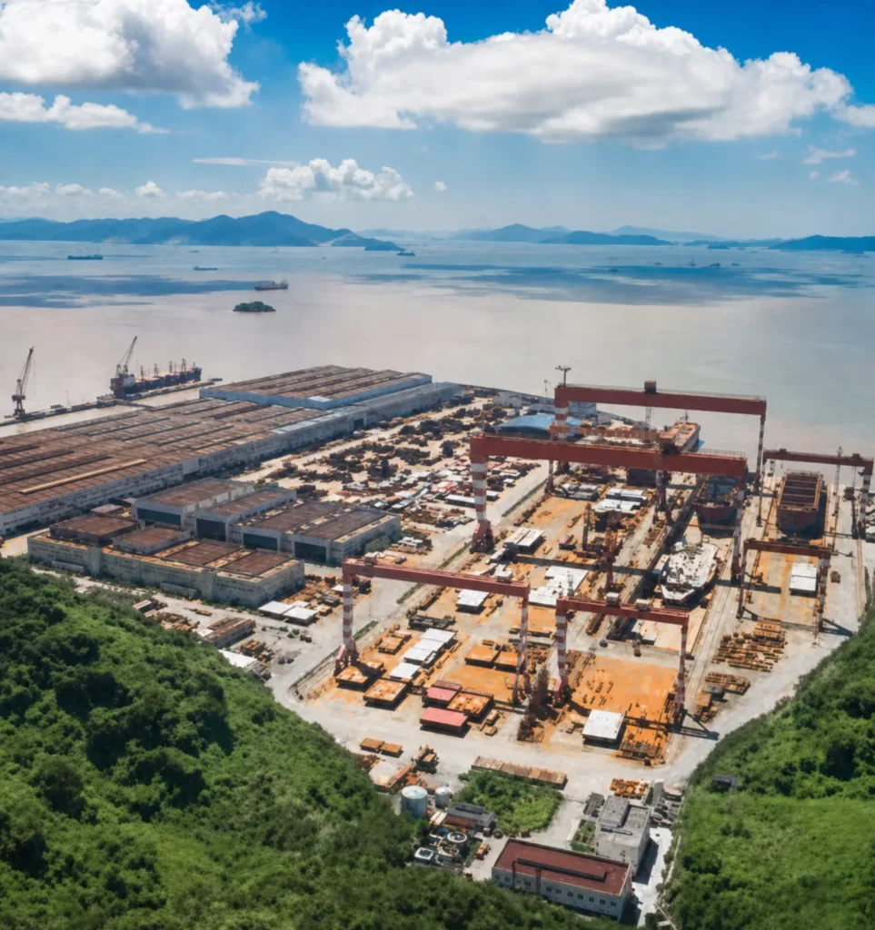 Shipyards & Marine FabricationPlate fabrication, block assembly, hall-to-yard transfer and outfitting each create a different movement boundary.
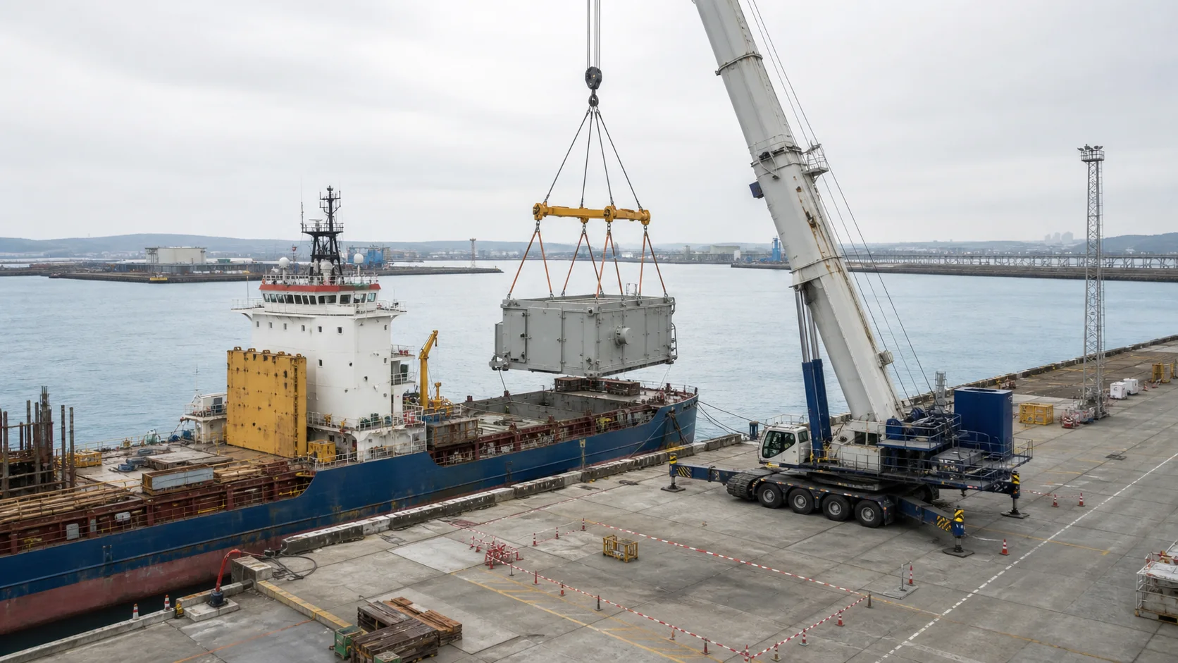
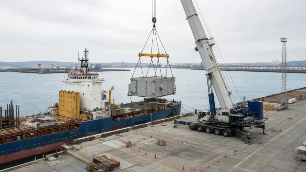 Ports & Marine TerminalsVessel interface, quay transfer, yard storage and landside hand-off define whether each cargo stream can move safely and predictably.
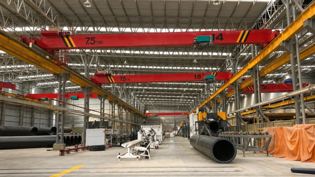 Machinery Manufacturing & Service WorkshopsReceiving, machine service, precision assembly and repair routes make access and positioning as important as lift.
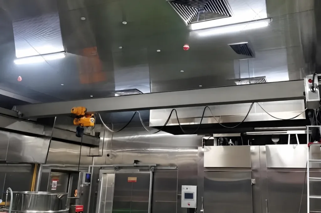 Food & Beverage ProcessingMaterial condition, cleaning access, short maintenance windows and packed-product flow shape the work.
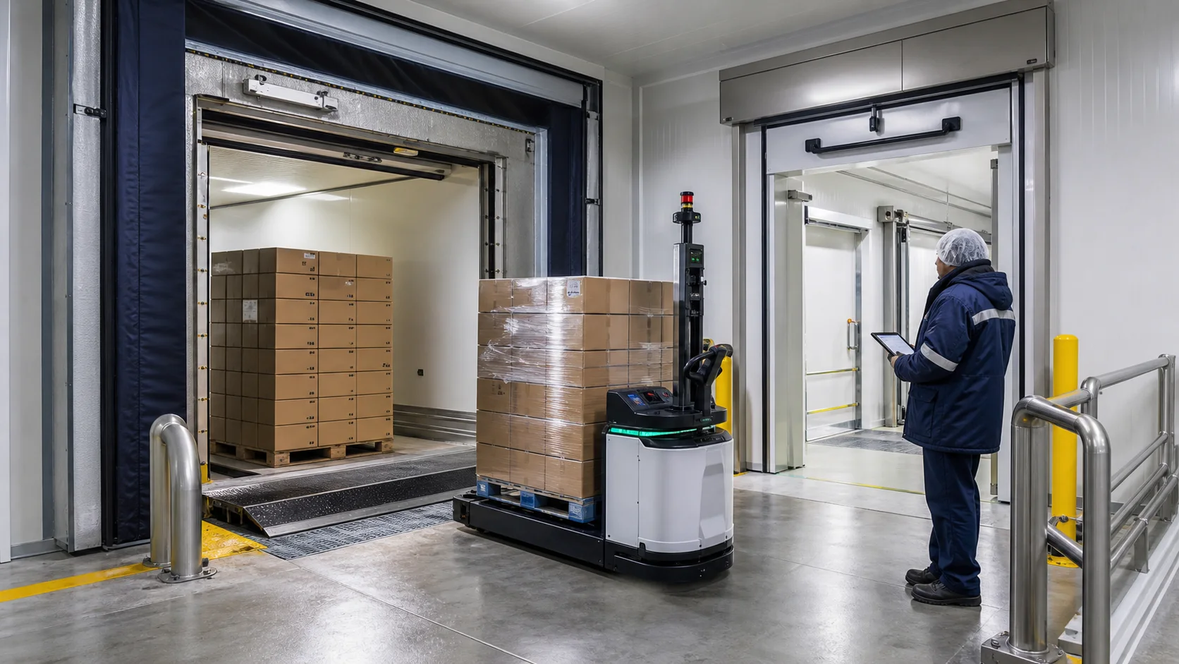
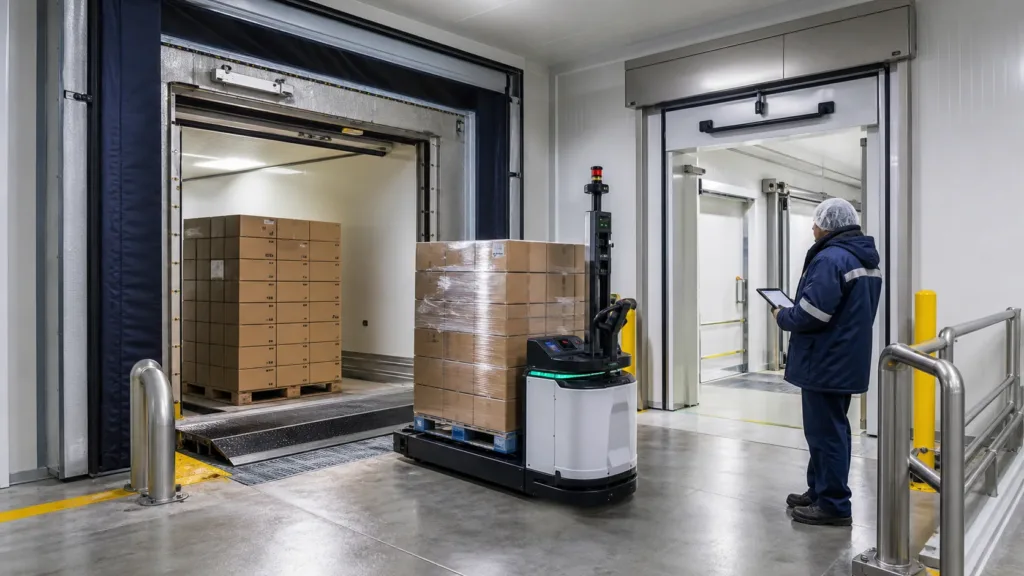 Cold-Chain Storage & DistributionTemperature-controlled receiving, zone transfer, storage and dispatch must preserve product condition without exposing people or flow to avoidable delay.
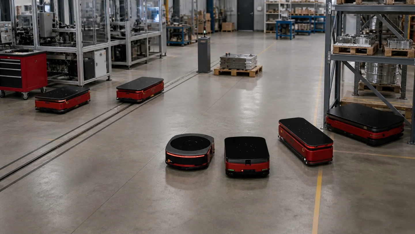
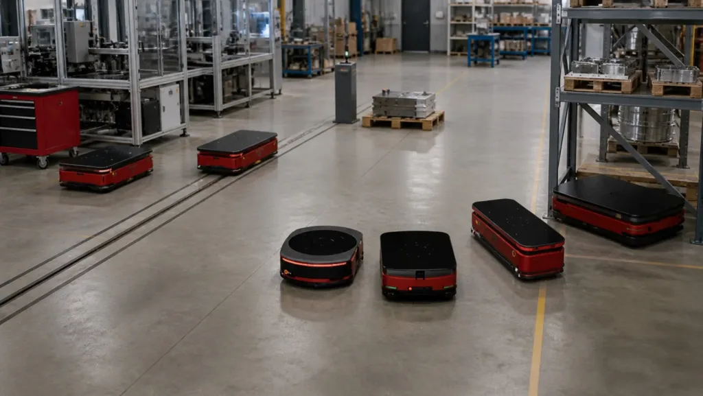 Warehousing, Distribution & IntralogisticsInbound verification, replenishment, consolidation and dock hand-off determine whether inventory moves predictably.
KEEP THE LINE SUPPLIED, NOT CROWDED.
In a takt-driven environment, a load must arrive in a usable orientation, at a known time and without occupying the operator's working envelope.
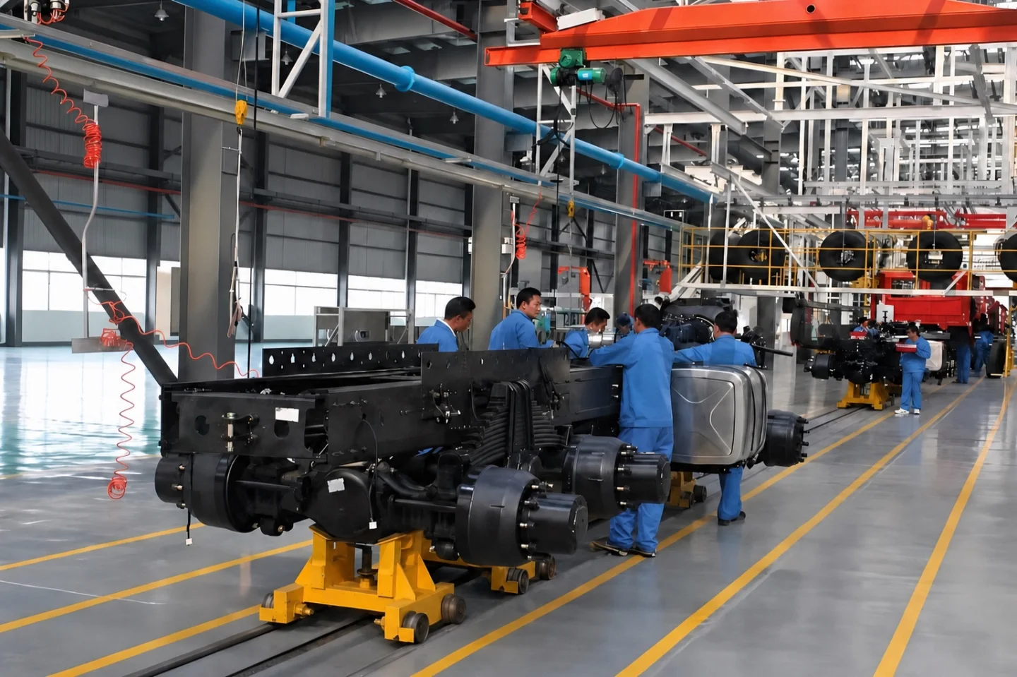
PUT THE RIGHT TOOL AT THE PRESS, ON TIME.
Press tooling and dies must leave storage, reach the correct press, be exchanged safely and return without turning a changeover into a production interruption. Route certainty, interface geometry, tool orientation and waiting space are more useful starting points than a generic lifting category.
Discuss tool change- Press tools / dies / fixtures
- Storage → press → return
- Changeover window & positioning
- Tool mass and centre of gravity
- Changeover window
- Storage-to-press route
- Cart or bolster interface
- Press clearance
- Positioning repeatability
Bay lifting coverage, local precision positioning and transfer support along the tool route.
PRESENT THE PART WHERE THE OPERATOR CAN USE IT.
Subassemblies, fixtures, battery modules, powertrain components or body parts must arrive at a workstation in the right orientation and when the operator can accept them. Moving a part to a line is not the same as presenting it safely for assembly, inspection or fastening.
Discuss line-side supply- Components / fixtures / modules
- Buffer → workstation → assembly
- Takt, reach & orientation
- Part geometry
- Handling orientation
- Line-side buffer
- Takt time
- Operator reach
- Fixture interface
Workstation or jib coverage, ergonomic hoist/manipulator path and a replenishment route beyond the cell.
CONNECT WORK CELLS WITHOUT LOSING PRIORITY.
A part may leave a machining or subassembly cell, wait for test, then enter final assembly while other materials share the same floor. The discussion is about route priority and hand-off ownership when a station stops or a quality hold interrupts the normal sequence.
Discuss inter-zone flow- Assemblies / test fixtures / carriers
- Cell → test → final assembly
- Queue logic & shared routes
- Origin/destination sequence
- Queue locations
- Part protection
- Shared routes
- Quality hold
- Recovery process
Transfer carts, AGV/RGV integration, overhead zone coverage and defined movement permissions.
SERVICE THE ASSET WITHOUT CLOSING THE LINE.
Motors, fixtures, conveyors and robot end-effectors must be removed, repaired and returned without extending a production-area closure. A credible maintenance route includes safe removal, isolation, temporary parking and a return path that does not compete with active production.
Discuss maintenance- Motors / fixtures / service parts
- Line asset → service bay → reinstatement
- Access & downtime window
- Component mass
- Access height
- Maintenance window
- Isolation boundary
- Laydown location
- Return route
Service-bay lifting, local jib or workstation coverage and modernisation of a constrained existing arrangement.
WHY THIS INDUSTRY NEEDS ITS OWN HANDLING LOGIC.
Automotive material flow is governed by time and presentation. A die must reach the right press inside a defined change window; a subassembly must arrive at line-side in the orientation the operator or fixture can accept; maintenance components must leave the line without turning a short intervention into a long closure.
The handling discussion therefore connects tooling storage, press interfaces, line-side buffers, inter-zone movement and service access. The best concept is not necessarily the fastest device: it is the route that protects takt, preserves operator space and provides a clear recovery rule when one station stops.
- 01
TAKT AND CHANGEOVER
Handling time is measured against the line or press window, not as an isolated crane cycle.
- 02
USABLE ORIENTATION
The load must be presented to a bolster, fixture or operator in the correct position and direction.
- 03
SHARED FLOOR SPACE
People, carts, AGVs, forklifts and maintenance teams often compete for the same route and buffer.
Four moments.
One material flow.
Use the route below as a first technical map. Each moment changes what needs to be measured, protected, timed or handed over.
PUT THE RIGHT TOOL AT THE PRESS, ON TIME.
Press tooling and dies must leave storage, reach the correct press, be exchanged safely and return without turning a changeover into a production interruption. Route certainty, interface geometry, tool orientation and waiting space are more useful starting points than a generic lifting category.
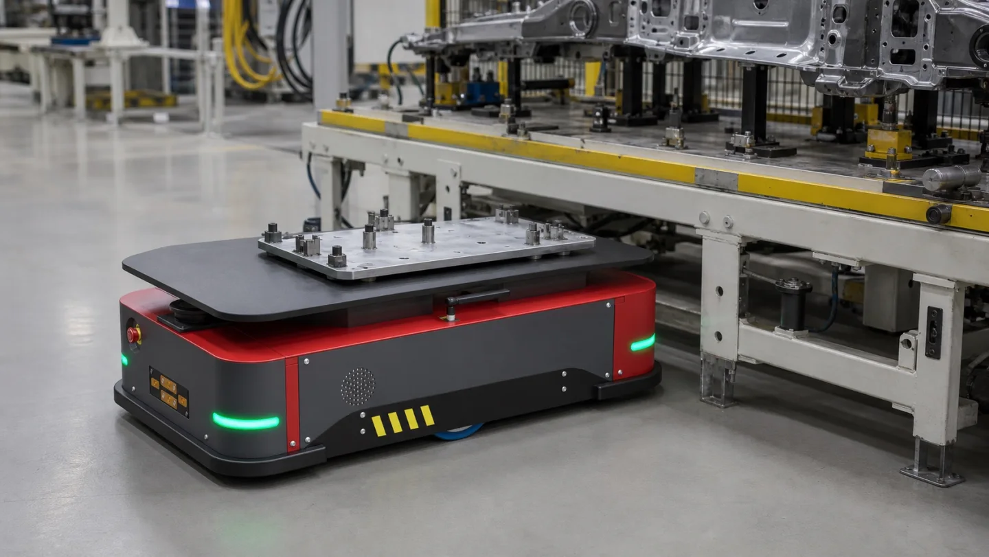
PRESENT THE PART WHERE THE OPERATOR CAN USE IT.
Subassemblies, fixtures, battery modules, powertrain components or body parts must arrive at a workstation in the right orientation and when the operator can accept them. Moving a part to a line is not the same as presenting it safely for assembly, inspection or fastening.
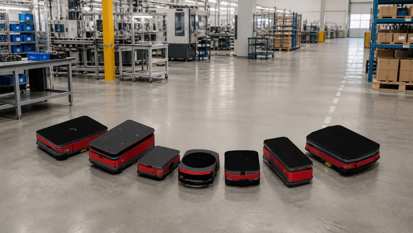
CONNECT WORK CELLS WITHOUT LOSING PRIORITY.
A part may leave a machining or subassembly cell, wait for test, then enter final assembly while other materials share the same floor. The discussion is about route priority and hand-off ownership when a station stops or a quality hold interrupts the normal sequence.
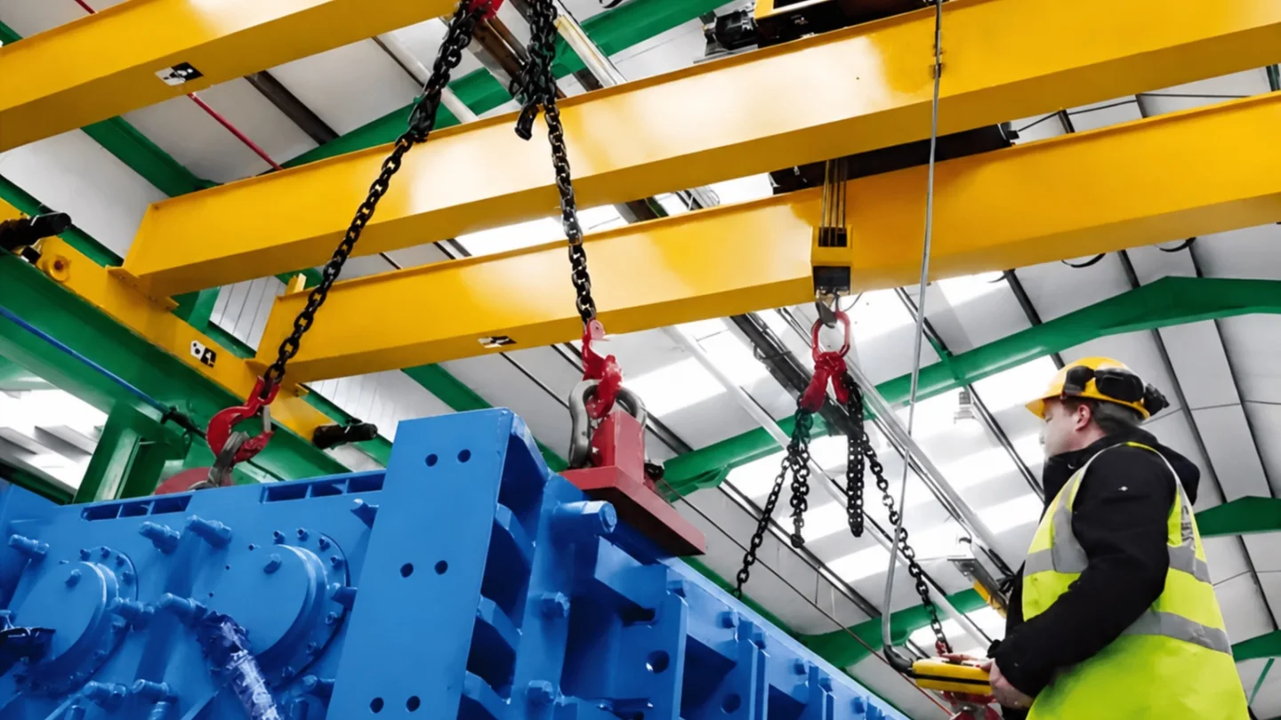
SERVICE THE ASSET WITHOUT CLOSING THE LINE.
Motors, fixtures, conveyors and robot end-effectors must be removed, repaired and returned without extending a production-area closure. A credible maintenance route includes safe removal, isolation, temporary parking and a return path that does not compete with active production.
What changes
the concept?
- A
TOOL INTERFACE
Map the die, cart, bolster, storage rack and press hand-off as one controlled sequence.
- B
LINE-SIDE BUFFER
Define how much material can wait without reducing operator access or hiding shortages.
- C
POSITIONING AND CONTROL
Match speed and fine positioning to the fixture, not only to the travel distance.
- D
STOP AND RECOVERY LOGIC
Specify priorities, safe waiting points and the route used when a cell or transfer device is unavailable.
Choose the equipment.
Then add the operating constraint.
Explosion protection, cleanliness, electrical insulation, availability, heat and automation can change components, controls, verification and acceptance across more than one product family. Treat these as project requirements, not as separate equipment categories.
Explosion-Protected Lifting
Classified gas or dust zone, group and temperature classChanges permitted motors, brakes, enclosures, wiring, controls, documentation and acceptance evidence.Define this requirement02Clean & Controlled Environment Handling
Cleanliness class, particle limits, material and lubrication restrictionsChanges exposed surfaces, materials, lubrication, enclosure, cleaning access and contamination controls.Define this requirement03Electrically Insulated Lifting
Voltage context, required insulation points and contact riskChanges the insulation architecture, monitoring, component separation and configuration-specific verification.Define this requirement04High-Availability & Redundant Lifting
Failure consequence, required recovery time and maintenance accessChanges drive and brake architecture, fallback states, maintainability and proof of continued availability.Define this requirement05High-Temperature & Molten-Material Handling
Molten or high-temperature load, radiant heat and personnel exposureChanges shielding, cabling, control position, emergency strategy and protection of critical components.Define this requirement06Automation, Remote & Unmanned Operation
Remote or unmanned cycles, system hand-offs and fault recoveryChanges sensing, interlocks, permissions, recovery logic, interfaces and responsibility boundaries.Define this requirementBring the route,
not a perfect spec.
A layout, route sketch, load list, photos or process sequence is enough to begin. The first discussion identifies the operating boundaries, missing inputs and handling roles worth evaluating.
MAP YOUR HANDLING ROUTE- Form, dimensions, condition, attachment and stability
- Origins, destinations, waiting points, doors and crossings
- Sequence, buffer, cycle, peak flow and recovery
- Structure, floor, access, temperature, dust, hygiene or wind
- Signals, traffic, responsibility, verification and delivery boundary